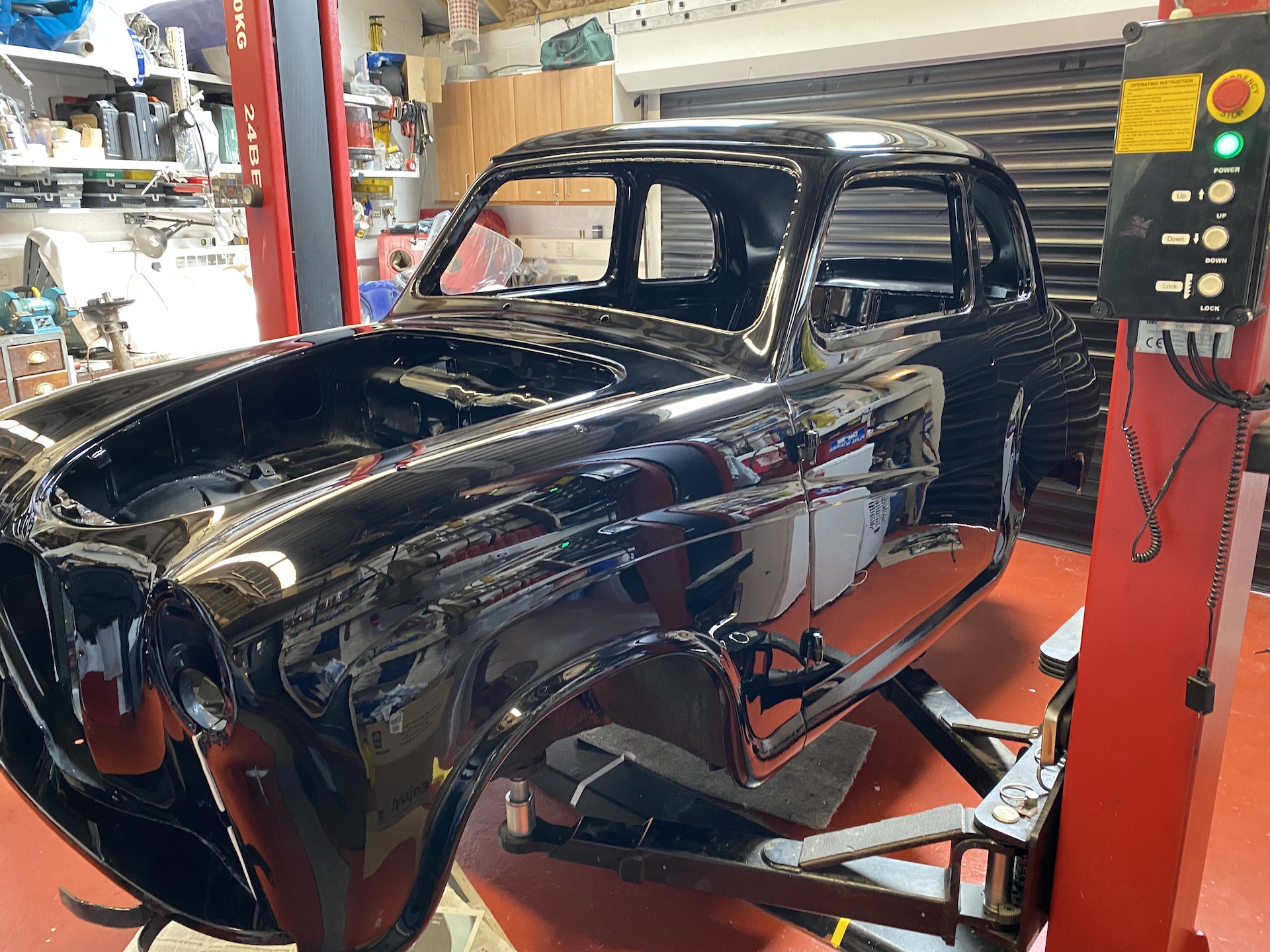
Hylton Reid describes in detail how he installed electrically-operated windows in the doors of his Austin A30 (pictured above), during his extensive programme of restoration and upgrades to the car.
(All words and images by, and copyright, Hylton Reid.)
Fitting electrically operated windows in the front doors of an Austin A30 or A35 is an obvious modification, since the windows only move up and down by finger pressure and there is no existing winding mechanism.
The project falls into 3 main parts:
- Finding, modifying and fitting an electric window regulator.
- Getting the electrical wiring into the doors, and to the window motor.
- Positioning the operating switches.
- Finding, modifying and fitting an electric window regulator.
There are many cheap, available, electrical regulators to choose from. I decided that I didn’t want the type that works on cables and pulleys, on the basis that they would be more difficult to modify.
I chose regulators from small cars with purely mechanical arms. My choice came down to the regulators from a Vauxhall Corsa C, not the D. (A viable alternative might be from a Kia).
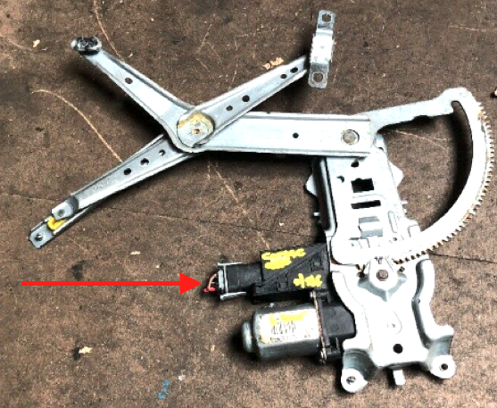
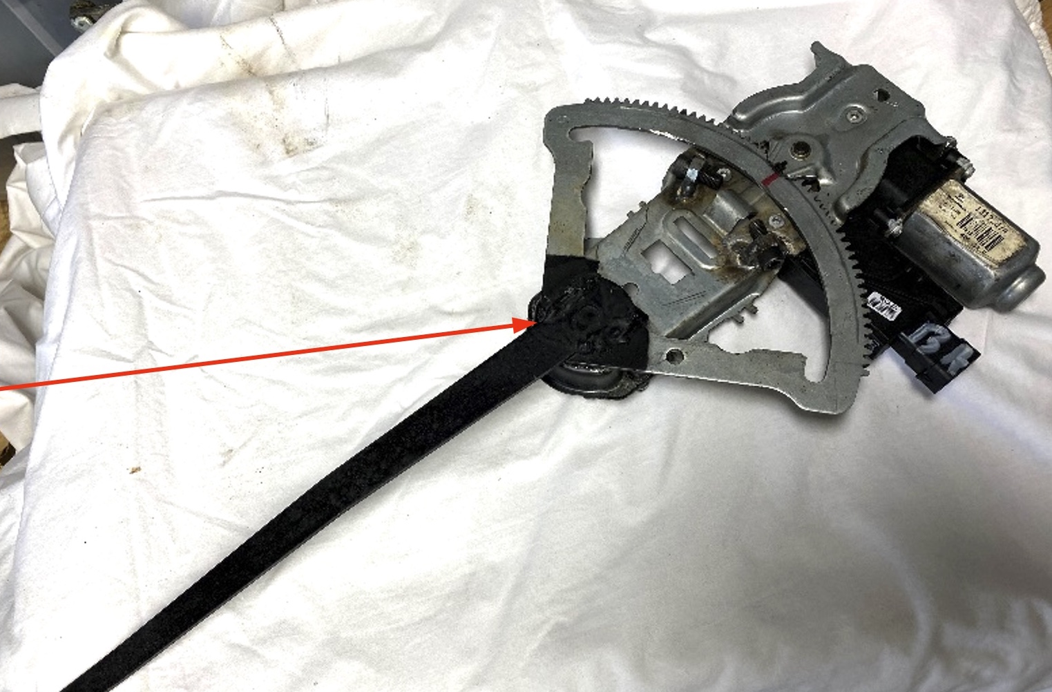
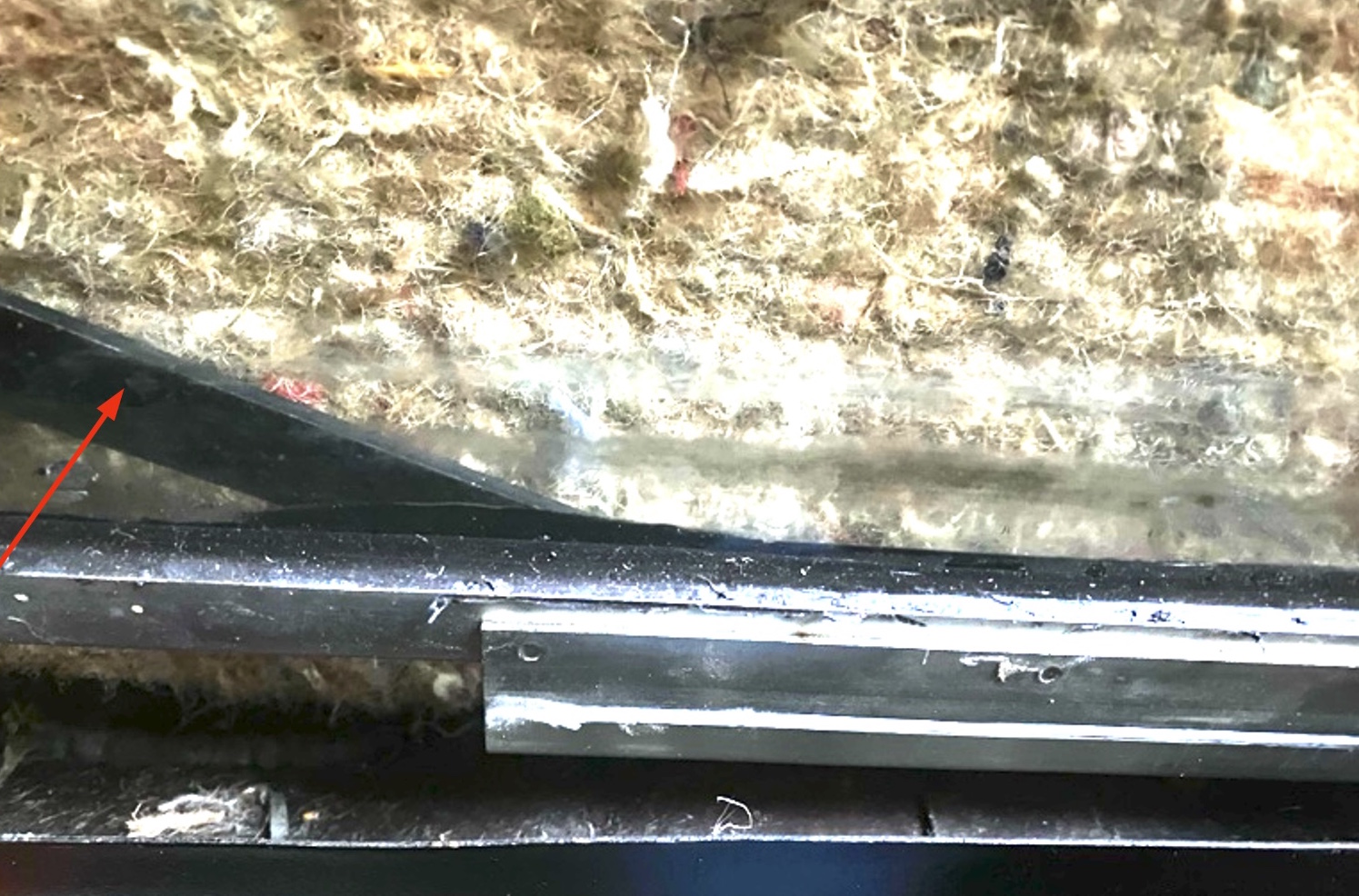
Fig 1 (above): This is how they come. This is the driver’s side; you will need one from the passenger’s side also – they are different (i.e. ‘handed’). If at all possible, try to obtain one which has the electrical connector plugged in to the control unit. This one has, you can just see it (arrowed) in the photo.
They are most useful when you come to the wiring it up, later on.
Fig 2 (below): This shows a close-up of the gear mechanism.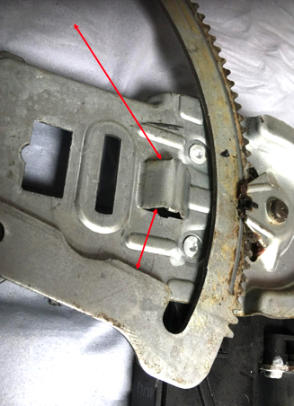
Highlighted by the red arrows are the mechanical stops that are built in to the base of the regulator. These prevent any strain being put on the glass when the window is closed, or on the frame when open. They are set to suit the window size of the Corsa. Needless to say, the A30 windows are smaller!
So, we need some additional mechanical stops to suit, preferably adjustable, so that the window can be precisely aligned and remove any inaccuracies resulting from the placing of the regulator inside the door.
Fig 3 (below): Here are the 2 adjustable stops fitted, as indicated by the red arrows.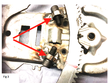
I used 1/4 x 1 inch UNF socket head bolts and nuts. Carefully align the nuts with the same angle as the stops on the gear mechanism before welding them to the frame.
I removed the 3 set screws holding the control unit to the frame to prevent damage during welding.
These appear to be in the approximately correct position. Once completed they will be locked in place with a locking compound (I used Loctite).
Fig 4 (below): Remove all of the original operating arms, but keep the various end pieces because some of them may be of assistance when fitting the operating arm to the window glass.
Remove the counter balance arm from the original door, discard the spring, and weld the operating arm onto the centre pivot of the regulator (as indicated by the red arrow).
You will have to re-grease the bearing after this because the heat of the welding will displace the original grease.
(The original mounting holes for the regulator are on the underside in this picture).
Fig 5 (below): The regulator can be mounted in the front of the door, just lower than the interior door handle, with the motor and electrical connector at the bottom.
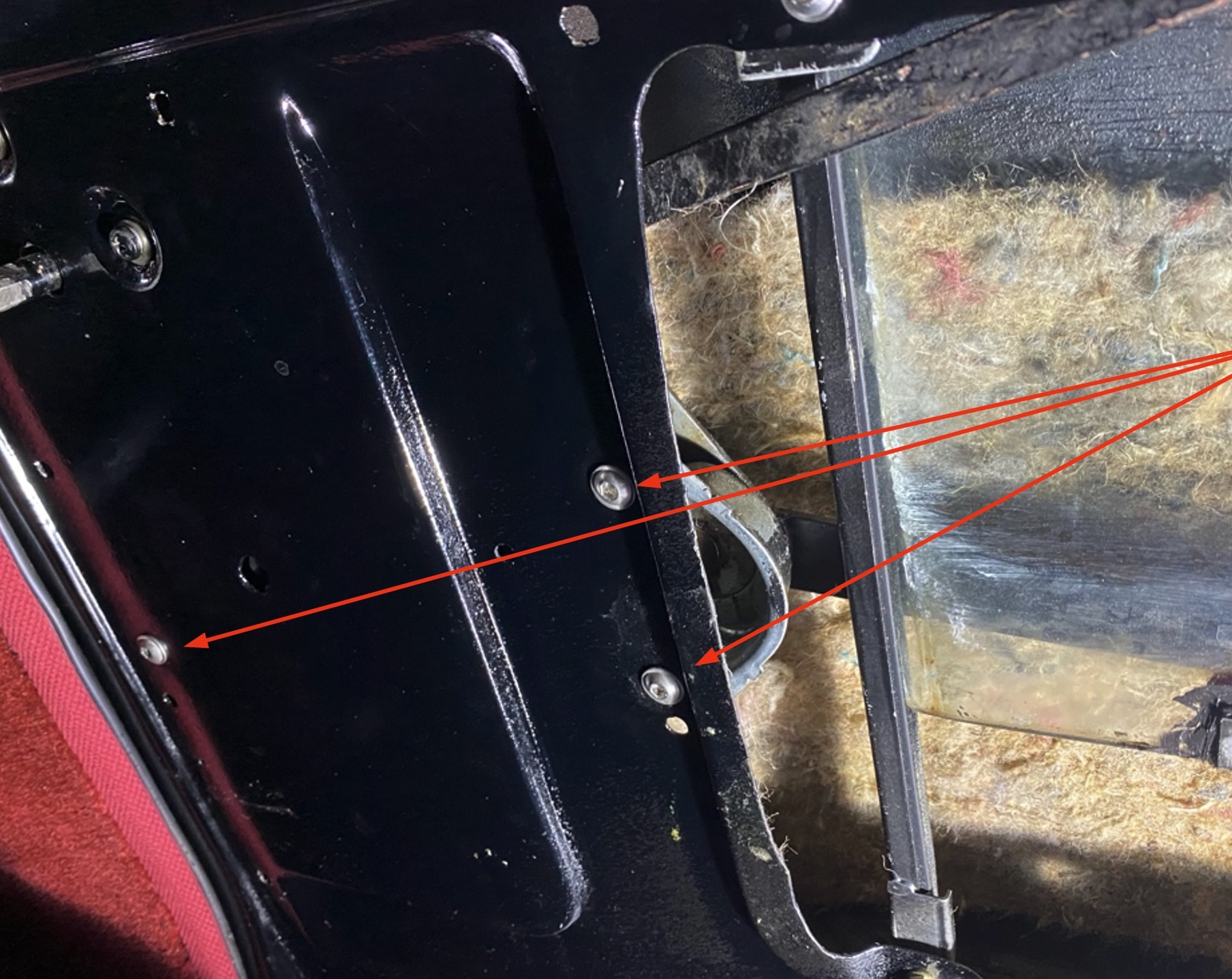
Use 3 (of the original 4) mounting bolts/screws, as indicated by the red arrows in the photo.
You can either weld nuts onto the inside of the frame, to take set screws, or use Rivet Nuts.
Rivet nuts are held in position by crimping, rather like pop rivets with threaded holes.
The next task is to connect the operating arm to the window glass.
There is no mechanism on the original glass which is suitable. I selected a Lower Glass Channel from an Austin Healey Sprite/MG Midget. These have a channel which fits onto the glass and another with a slider channel incorporating a plastic slider running inside it.
Fig 6 (below) shows the slider channel (as indicated by the lower of the two red arrows here),and the yellow plastic slider (shown by the upper red arrow in this illustration). Note the central hole, which takes the ball joint which is fastened into the hole at the end of the operating arm.
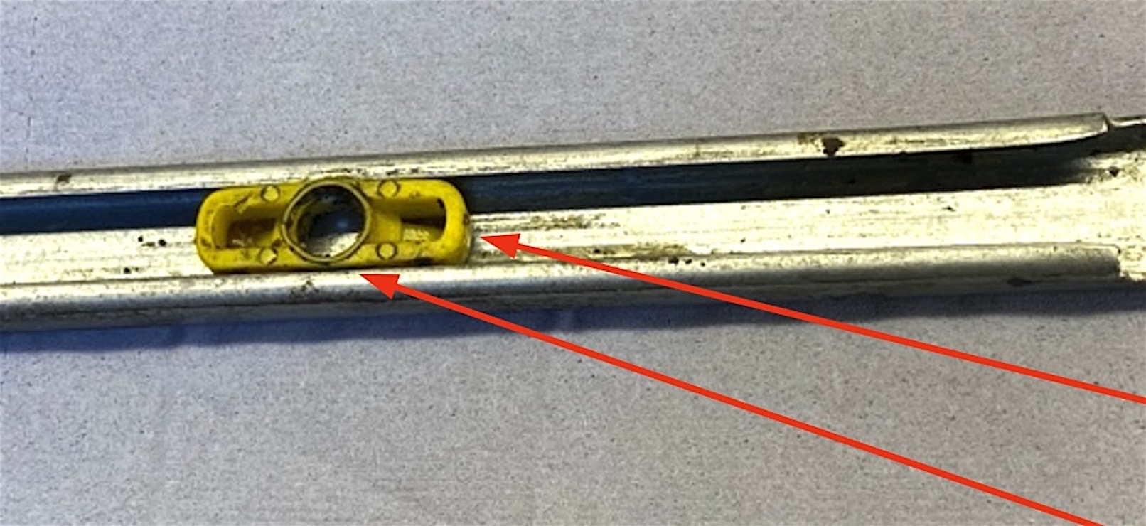
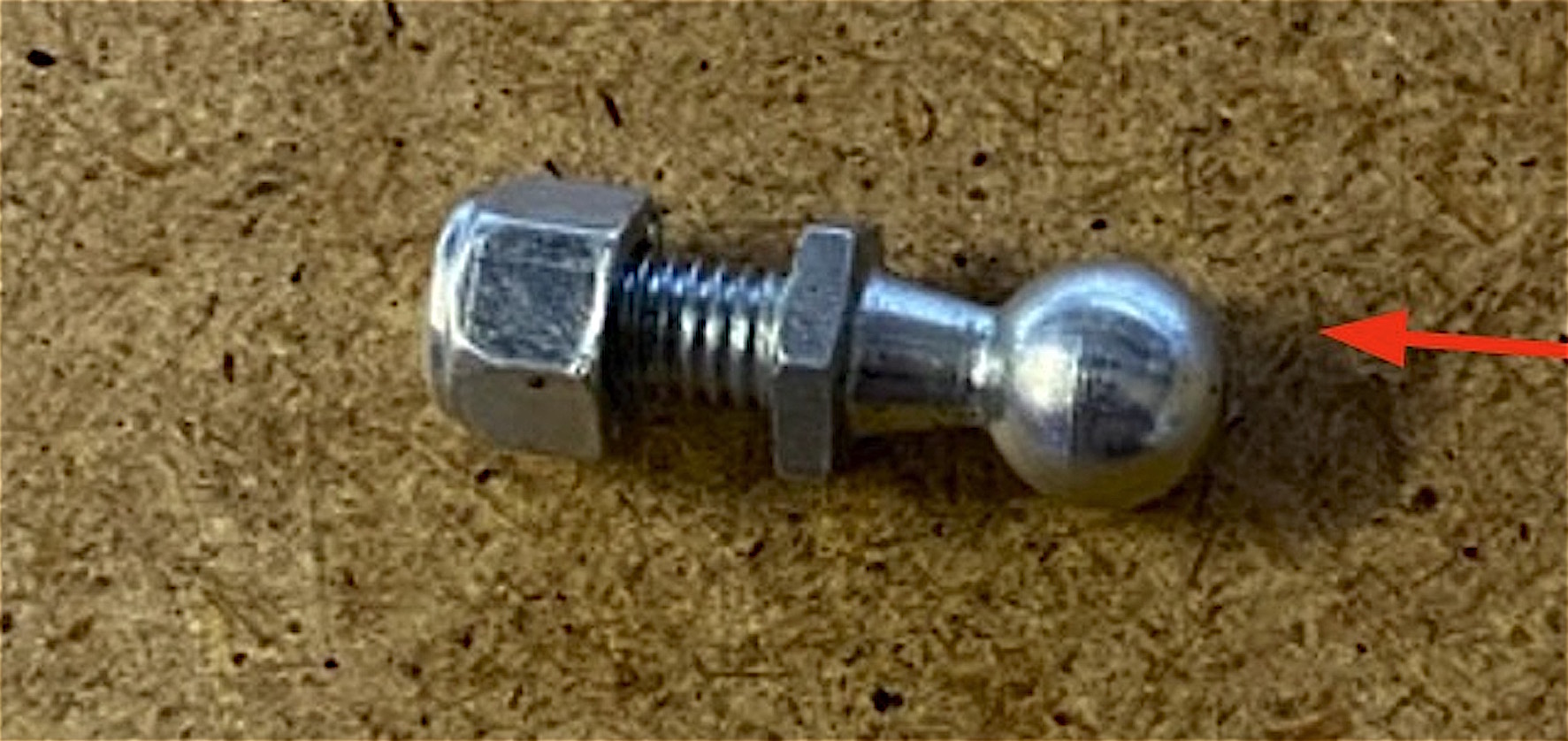
Fig 7: The ball joint (shown below, and just referred to), with the ball end (arrowed) that fits within the yellow plastic slider shown in the previous photograph…
It is difficult to see in Fig 8 (below), but the Glass Channel has been fixed to the window glass using black silicone sealant.
The slider channel is facing away from us in this picture, facing towards the door skin rather than the car interior. This is because the ball joint is pushed into the plastic slider from the rear.
The operating arm (indicated by the red arrow) can just be seen behind the glass channel.
Once the whole assembly is operating correctly, it is necessary to set the adjustable stops to their correct positions.
You need to adjust to arrive at positions in which no unnecessary strain is placed on the glass when in the raised position, and also of course the glass needs to be at the correct height when lowered.
Getting the electrical wiring into the doors, and to the window motor.
There is not sufficient room between the “A” pillar and the front of the door to permit wiring to be installed, as in most modern vehicles. So, we need to find another way.
The only connection between the vehicle body and the doors is the flexible strap securing the door at the lower end, used to prevent the door from opening too far. This is the only choice unless you want the wiring to be visible
Fig 9 (below): The webbing strap, shown removed from the door, and with the wiring incorporated.
Carefully drill the edge of the webbing with a 2mm drill and pass the 4 wires through the inside. The notch on the other end is to line up with the plastic tubing, see later.
Use modern, thin-wall cable, 0.5mm sq, rated at 11 amps.
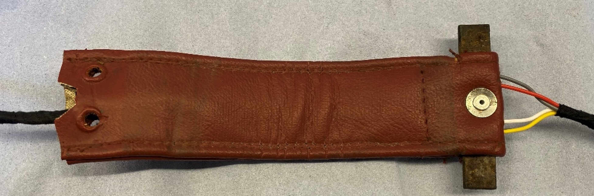
Fig 10(A) (below): The relevant wiring diagram…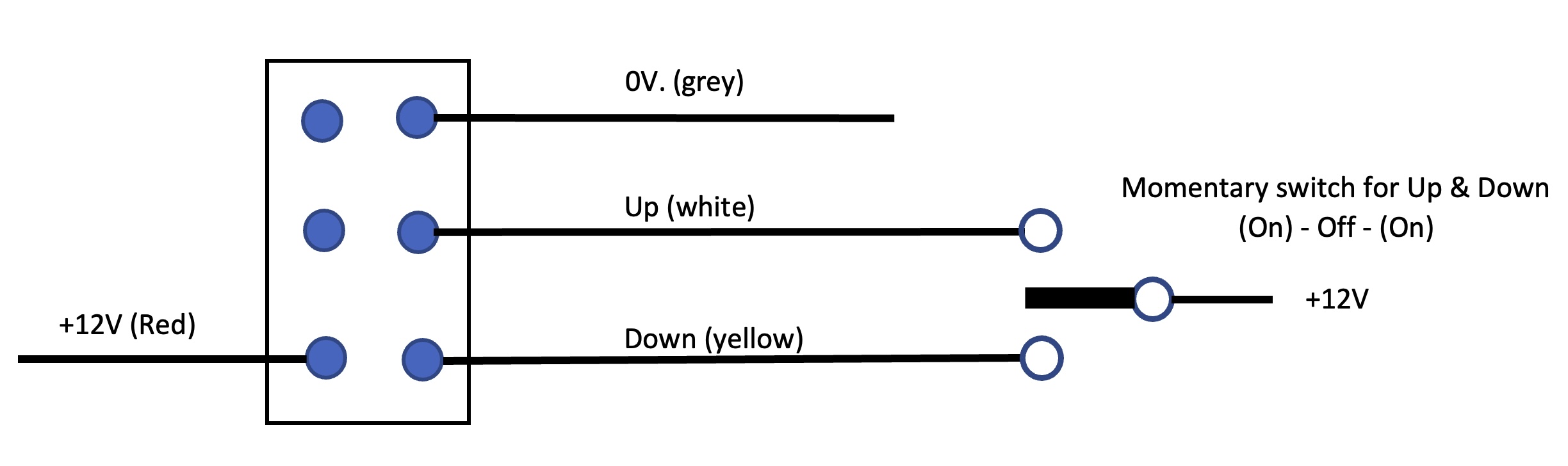
Fig. 10 (B) (Below): Because the switches are only for signals, they don’t need to be heavy current switches. I chose the small, 2A switches shown, which are easy to mount.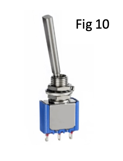 Fig 11 (Below): Getting the wiring from the car to the door.
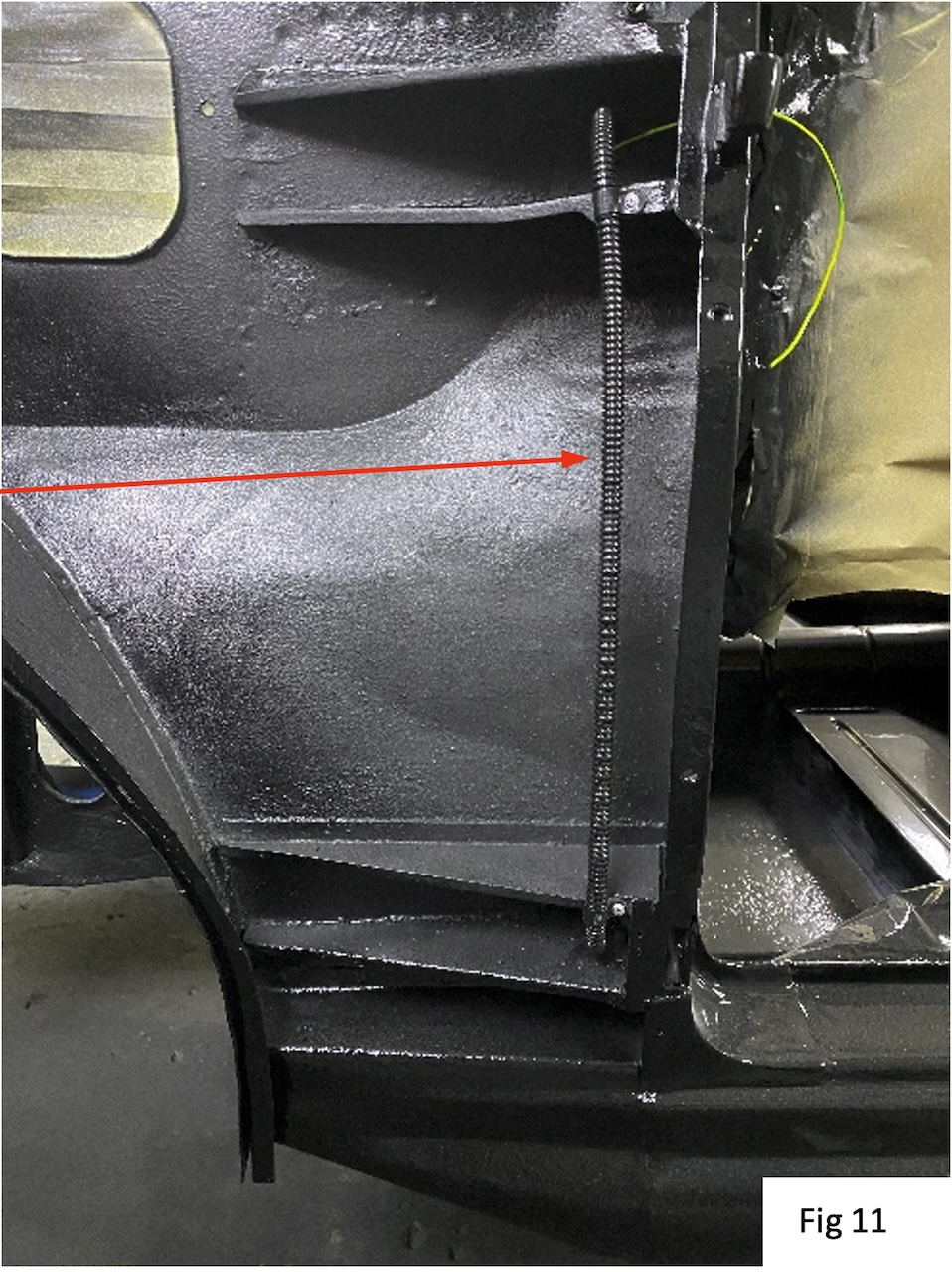
With each front wing removed, drill a small hole in the lower hinge strengthening web, to feed into the car interior. This hole should be central to the 2 securing screws for the webbing strap, hence the notch in the strap, to clear.
Insert a length of 7mm convoluted plastic tube (arrowed) between this hole and the one already provided at the top for the courtesy light cable, going onto the parcel shelf. Clip in place with some plastic “P” clips, screwed to the re-enforcing edges of the hinge webs.
Once the webbing strap has been fitted to the doors, the 4 window wires can be fed through this tube, back into the car.
Connect up the wires in the door to the electrical connector on the regulator, which you saved earlier.
Connect the other end to the switches and power supply underneath the dash.
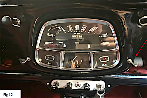
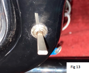
Fig 12 and 13 (below): I chose to mount the 2 switches where they could easily be reached.
I drilled 2 holes, 6.2mm, either side of the dash and about level with the oil pressure and ignition warning lights.
There is no reason why the switches could not be mounted in the doors themselves, if that is your preference. The connections to the regulator remain the same, but only 2 wires are needed through the webbing strap, Positive and Negative.
Latest Update
I understand that the webbing straps and internal wires, described here, are now available directly as complete units, from Robert Prinn (‘Austin Motors’); Tel. (02380) 600868; e-mail a30a35spares@gmail.com
Kim adds:
Further (previous) articles on Wheels-Alive from Hylton about upgrades to his A30 (and also applicable to A35s) are listed below; for direct links please enter ‘Hylton’ into the search box on the website, and the list will appear:
Installing ‘A’ frame rear suspension (April 2021).
Fitting a front anti-roll bar (January 2022).
BMC ‘A’ Series engine roller rocker valve gear, modifications and potential problems (November 2023).
In addition, Hylton has written a comprehensive feature on installing a Mazda MX5 gearbox to a Sprite/Midget (February 2021).
My thanks to Hylton for kindly allowing the use of his articles on Wheels-Alive.