Dave Moss has tackled the requisite work in this area on his own early Mini (1960 example), and passes on invaluable information to help other owners…
Though this feature primarily describes procedures to change an early Mini differential output shaft oil seal, it is likely to be helpful to anyone needing to remove and replace classic Mini driving flanges, drive shafts and inner and outer universal joints as well as various key suspension components.
Introduction
I have tremendous respect for the small team brought together by Alec Issigonis at BMC midway through 1956, to transform an ethereal paper concept, codename XC9003, into the Austin Se7en and Morris Mini Minor. It’s well documented that Issigonis was then brimming with suitable ideas, and BMC boss, Leonard Lord, unleashed that torrent by – reputedly – commanding him to come up with “something to drive these bubble cars off the road”. They were suddenly proliferating because petrol had breached the dizzy heights of 3s 6d (17.5p) a gallon (3.85p/litre) as a result of the Suez crisis…
Somehow, up to ten prototype cars were completed and tested well inside 3 years, powered by the A35’s 948cc A series engine (although production Minis were powered by an 848cc version of this motor). Yet other key mechanicals – notably the transmission and suspension – were completely new or heavily modified, testifying to a development work rate bordering on miraculous by 1950s car design and manufacturing standards. Ultimately over 5 million were sold worldwide, but the speed of progression left easy maintenance access low on the list of design priorities, which led to various problems in the 1960s, never mind now, over 66 years after launch.
Getting started
My 1960 848cc Morris Mini-Minor has a genuine BMC Gold Seal (remember them..?) gearbox, bought on main dealer service exchange, and fitted at home. The previous owner had run it dry of oil, so the car also got a crank regrind, new pistons, rings and shells, and plenty more besides.
Last summer I noticed drips of oil accumulating underneath, and inspection revealed an oil trail extending under the nearside floor pan. Getting stuck in with jacks and stands, it was clear oil was originating from the differential output shaft housing, connecting to the nearside drive shaft. unsurprisingly, the area was covered in a nasty-looking accumulation of oily road dirt, but the issue was characteristic of ageing oil seals typically found where rotating parts, oil and the outside world have demanded separation on cars for many years.
On the classic Mini, seeing a problem does not necessary equate to easy practical access to effect a repair without major unrelated work and a range of cuts scrapes and bruises to the hands and arms to prove it. In fifty years I have completed many mechanical jobs on Minis, gaining experience of foibles, eccentricities and possibilities on virtually all derivatives. Excluding engine and transmission internals, that experience has shown that a surprising range of repairs are possible -.if you are patient, determined, have the right tools – and don’t need the car until next week. But… I had never seen a leak here before, so renewing this oil seal was uncharted territory.
In such cases, my motto is to secure parts and generous supplies of de-greaser first, then carefully assess pros and cons of “engine out” or “job in situ”. Consideration covers working space and anticipated difficulties, and best available information – then simply choose and go for it. With anticipated parts obtained, and initial clean-up complete, I decided to attempt the job without engine removal, on the basis that if it proved impossible, most work to reach the impasse would have been necessary anyway simply to get the engine out.
But… there was a wild-card deciding factor: removing/refitting the driving flange nut on the differential output shaft. The BMC workshop manual, (AKD4935B) demands 70lb/ft of torque here, plus more to align to the next split pin hole. This is pretty tight. and not easily achievable with engine/transmission loose on the bench… but with the car on stands, a “special tool” can be made to hold the driving flange steady against the ground while torque is applied for removal/refitment of the nut.
Dis-assembly
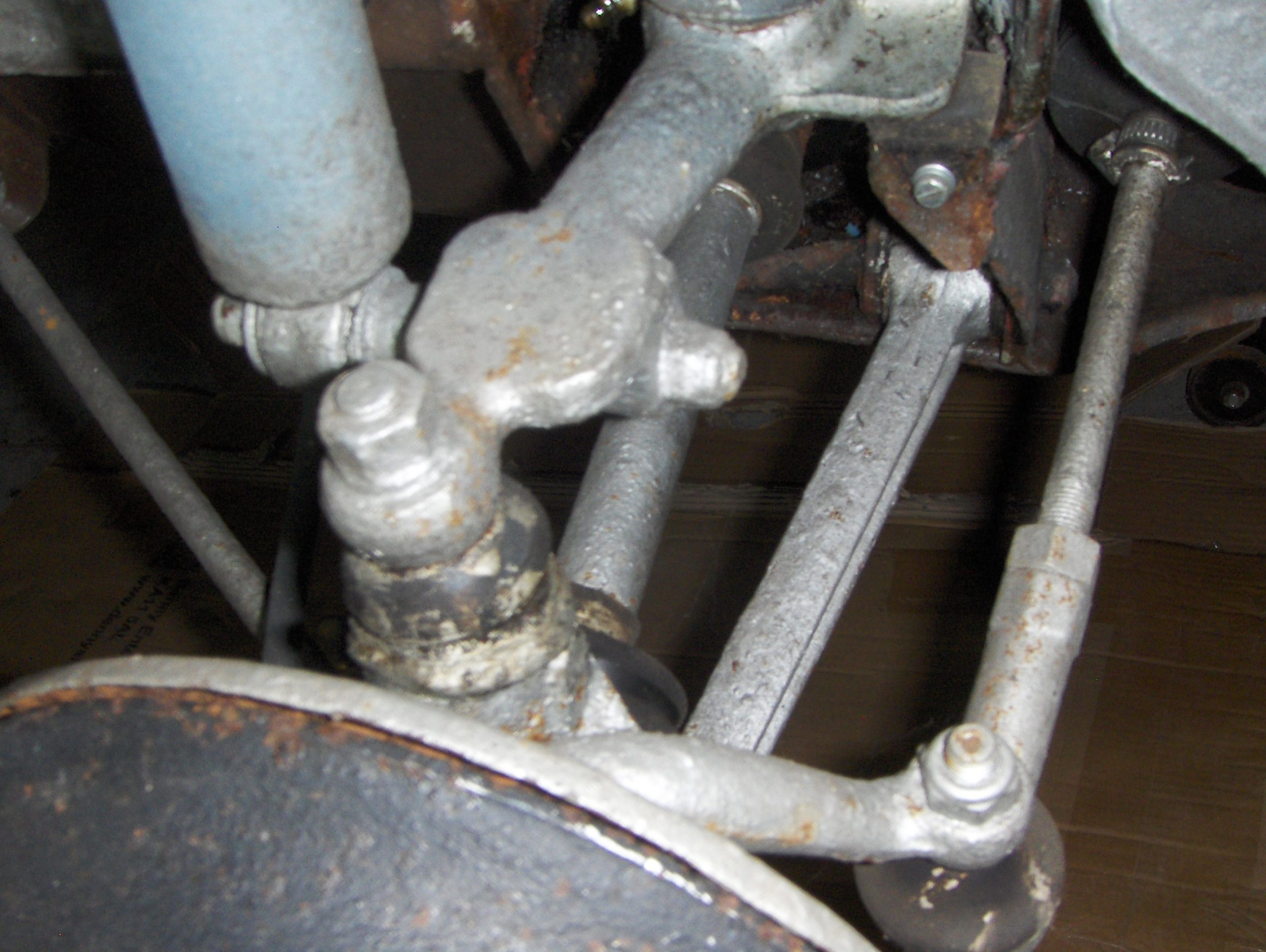
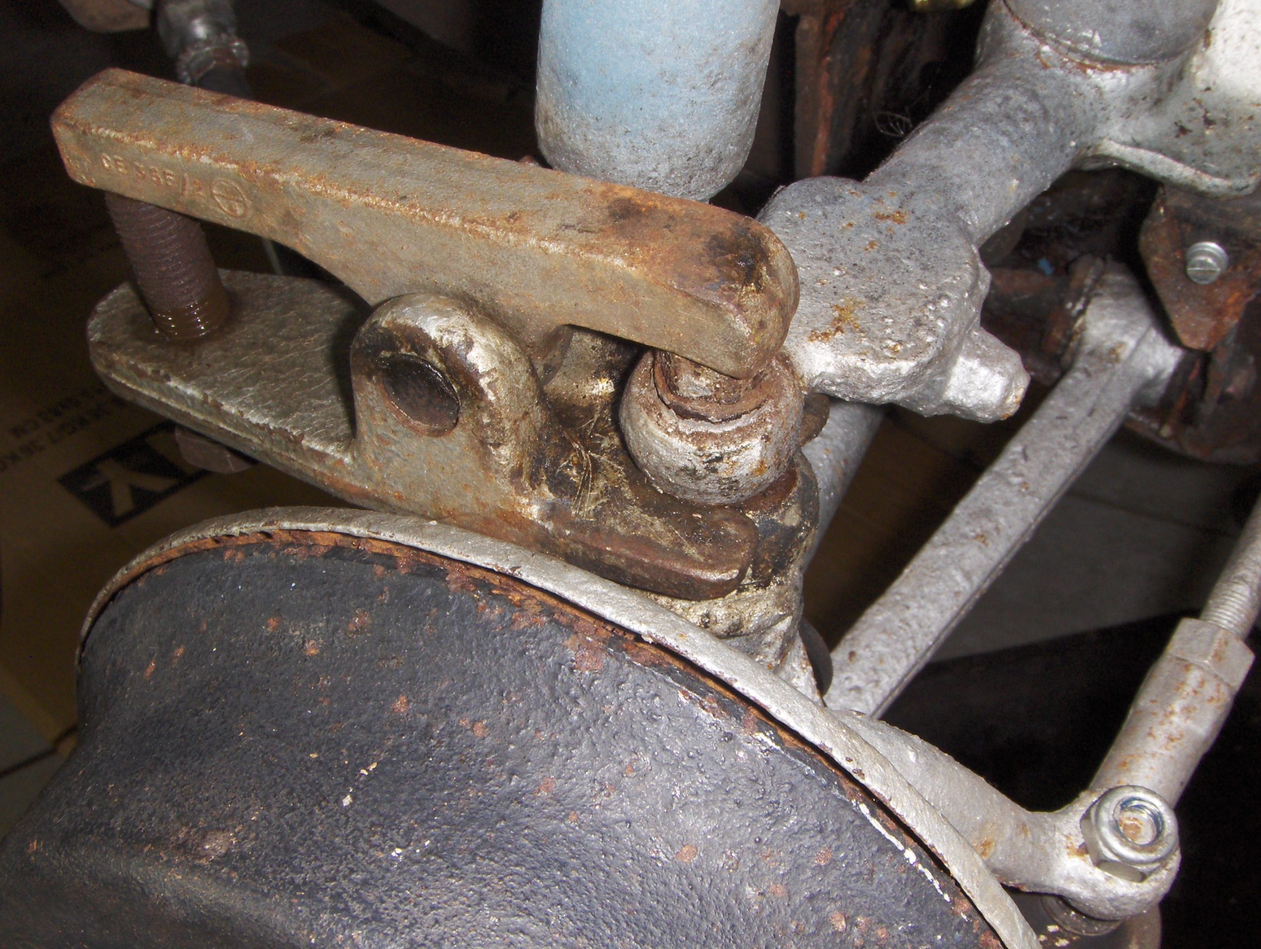
Firmly chock the rear wheels, and jack up to fit stands for rigid, stable support at the chosen front working height. Check the support is entirely adequate – then check it again – and use the jacks to provide auxiliary support. Back off brake adjustment on your chosen wheel, and remove it – after carefully checking for swivel pin joint wear. Remove the track rod end nut, and use a splitter (scissor type is best) to crack the joint, and check its condition. Then split the lower swivel pin joint, then the upper; leave the nuts on temporarily, but if anything needs adjustment or replacement here, order parts to address it during re-assembly.
Undo and remove the bolt securing the tie rod to the lower suspension arm, then the nut, bushes and washers at the forward end, and remove the tie rod. Collect all components and note the order to refit items if necessary. Note that replacing the bushes is recommended, so add them to your shopping list.
Next, brake system disconnection. All early Minis have single circuit brakes, on which the front procedure is straightforward – but irritatingly fiddly for different reasons on each side. Remove the master cylinder cap and place a small, thin, clean plastic bag over the filler – then replace and tighten the cap. This should hopefully prevent (or at least minimise) fluid leakage on disconnecting the system. The cylinder outlet pipe can be disconnected, but all fluid remaining in the pipe will drain down, and create a mess in your work area… My job required nearside disconnection, where, looking through the small rectangular hole (below the radiator vents) in the inner wing, observe a large nut (attaching the wheel’s brake hose to the subframe) and emerging from the left hand side’s brake pipe – with union tightened into the hose itself. Both must be removed, which is rarely easy – and there’s invariably plenty of dirt around in this inaccessible spot – but it is vital that all braking components to be re-used are kept absolutely clean… so prepare a clean end cap to fit over the brake union when released, and a clean plug to place in the revealed hose hole.
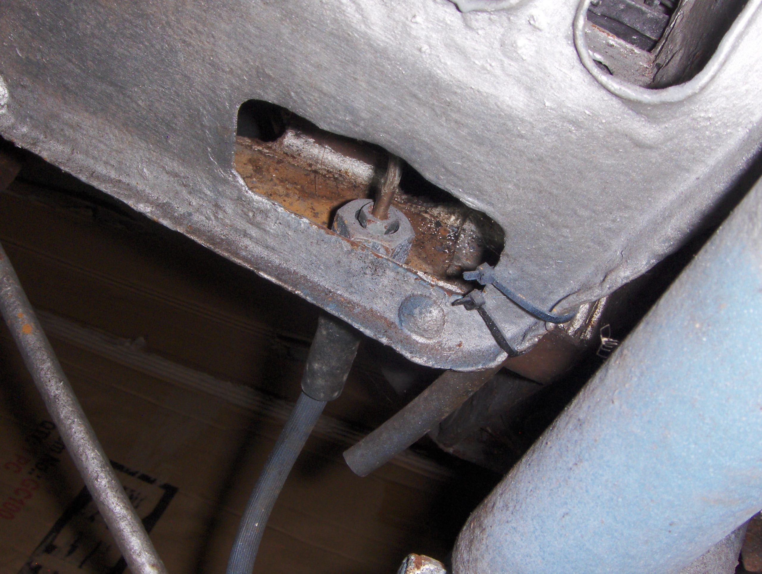
The brake pipe union needs an unworn, close fit 7/16 inch open ended spanner, applied with care to ensure it doesn’t slip. (Kim adds… Alternatively, purpose-designed ‘split’ ring spanners designed for work on brake and fuel system pipework are available, and provide positive location/effective grip). The union could be part submerged into the much larger brake hose nut, and will need quite a high removal force. If this union is rusted or won’t budge, small locking vise grips might get a start, but often it’s simpler just to cut the pipe, probably employing patience, pliers – and metal fatigue. If it can be saved, seal the pipe end, but if cutting is required, remember that big nut will still need removal, so cut to allow your spanner, ring key or socket easiest unobstructed access. Again consider whether new parts – e.g. a bleed nipple. brake pipe, hose nut, brake hose and associated shakeproof washer are required, and order up as needed.
If the flexible hose is serviceable on removal, plug it, and secure to the hub kink-free with tape. Select neutral and, back underneath, rotate the hub to remove the four locking nuts securing the two outer U bolts around the inner driveshaft flexible joint (“doughnut”). Withdraw the U bolts ready for cleaning and examination.
In the absence of a strong and willing assistant (well, they’re never around when I need them…) position a trolley jack at right angles to the car set level with the bottom of the hub. Ensure the top ball joint nut is loose but in position on the upper swivel, that the track rod is disconnected, and the lower swivel pin nut is removed. Don’t be caught unawares here – the hub’s universal joint will allow it to swing upwards /downwards /sideways when released from the car… and this assembly is quite heavy. Be sure also to avoid damaging the outer or inner driveshaft rubber boot. Manoeuvre the hub upwards a little while pushing down on the lower suspension arm to release it. Move it around the lower arm, to rest on the suitably adjusted jack (still held finger tight in the top swivel)
With the inner end of the drive shaft already released, on removing the top swivel nut, gentle and slight pulling of the hub outwards on the jack will cause the inner drive shaft section to drop onto the subframe hole rim, leaving the drive shaft roughly parallel to the floor line.
Observation might suggest that it is impossible to get the released driving flange through the subframe hole to remove the assembly from the car… but it isn’t. Proceed as follows. Ensure plenty of downward travel is available on the trolley jack. Position the jack (carrying the hub) just forward of the lower suspension arm (and also forward of the driveshaft’s running line) Carefully rotate the hub so a longer driving flange face is sloping backwards just a few degrees short of vertical. Under the car, with a medium screwdriver, visibly check that the bottom (curved) face of the flange is resting centrally in the subframe aperture, close to the inside face. At this stage the top left of the flange already looks likely to fall though the top left of the aperture. Adjust with the screwdriver to optimise this position, and return to the jack.
Watching the external aperture closely, gently lower the jack, and the top corner of the flange should appear through the hole as the jack descends. It may be necessary to move the lower suspension arm out of the way – and also to hold the jack position midway, to ensure alignment of aperture and flange from underneath – but with the jack near ground level, the flange should simply lift out of the aperture, and the jack used to move the entire assembly elsewhere.
Next, remove the four locking nuts on the two remaining bolts and remove the doughnut, again saving everything for inspection. In my case everything remaining required a serious clean-up. so de-greaser was applied to the seal housing, flange, retaining nut and split pin, and surrounding area.
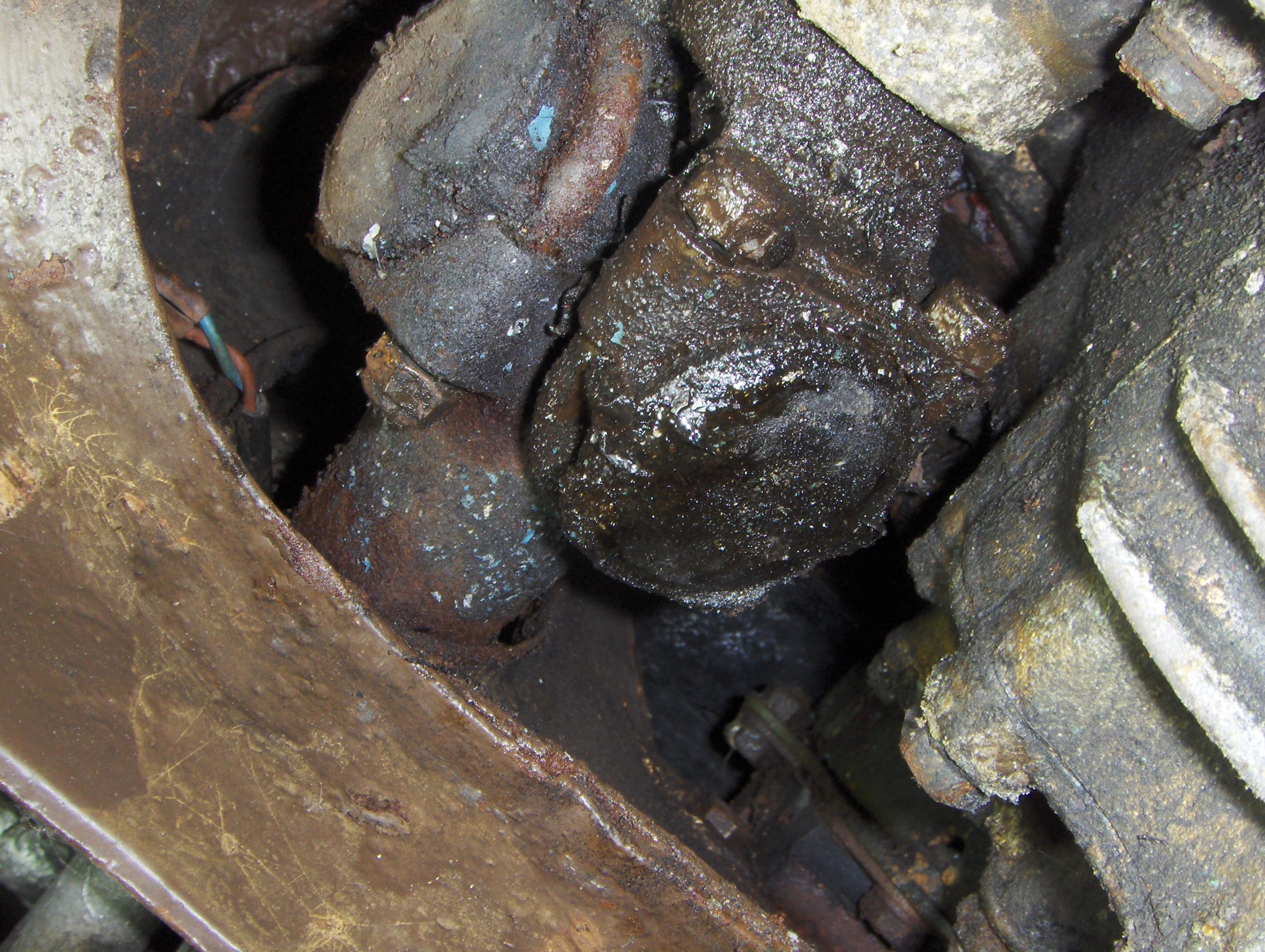
The revelation… Major BMC quality control failure revealed… 56 years on
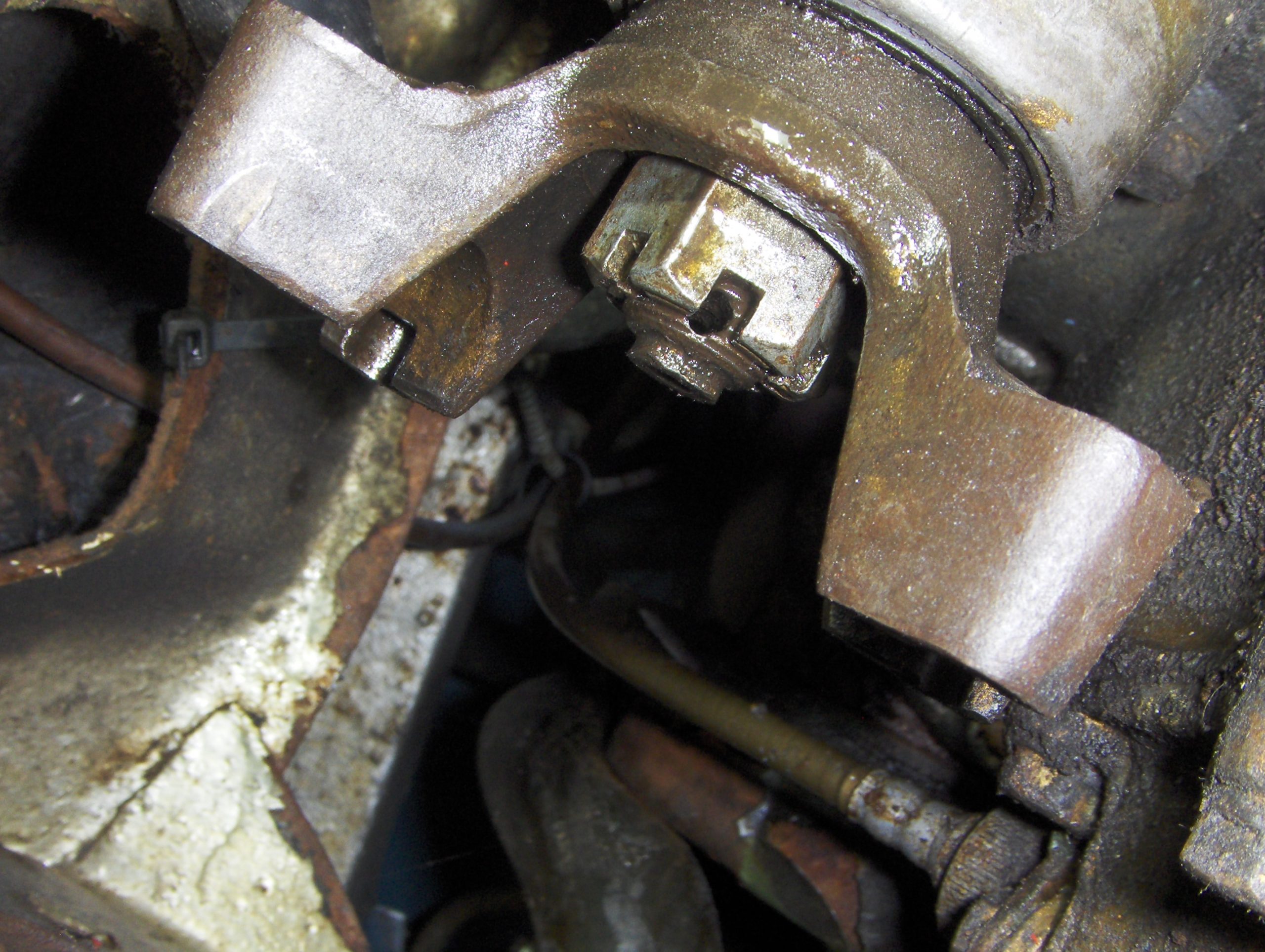
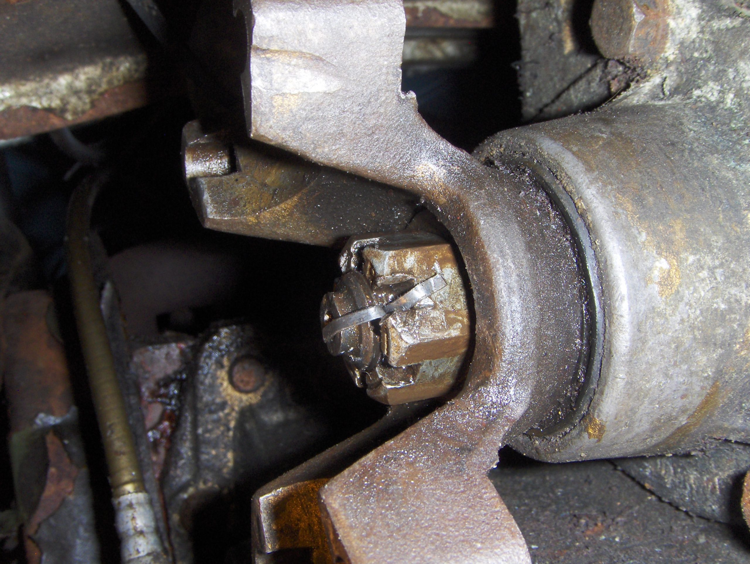
The next step is draining the engine/transmission oil, but I didn’t quite get that far. Removing the de-greaser residue, up close, with now spotlessly clean components fully illuminated, it was clear… the oil seal wasn’t leaking. Surprisingly, oil was very slowly, but definitely, weeping out from behind the driving flange securing nut. With daunting thoughts of sourcing obscure differential components for a car built 66 years ago, in a series known to have had at least four different transmission part numbers in its first year – I reached up to gauge flange spline wear through movement… and, observing closely, bizarrely the revealed movement suggested the nut itself appeared loose – and, sure enough, it was not even finger tight – against a 70lb/ft workshop manual torque figure! This transmission is a complete BMC Gold Seal unit, service-exchanged at a main dealer in 1969, which had run reliably without any attention until the slight oil leak, which started in 2023.
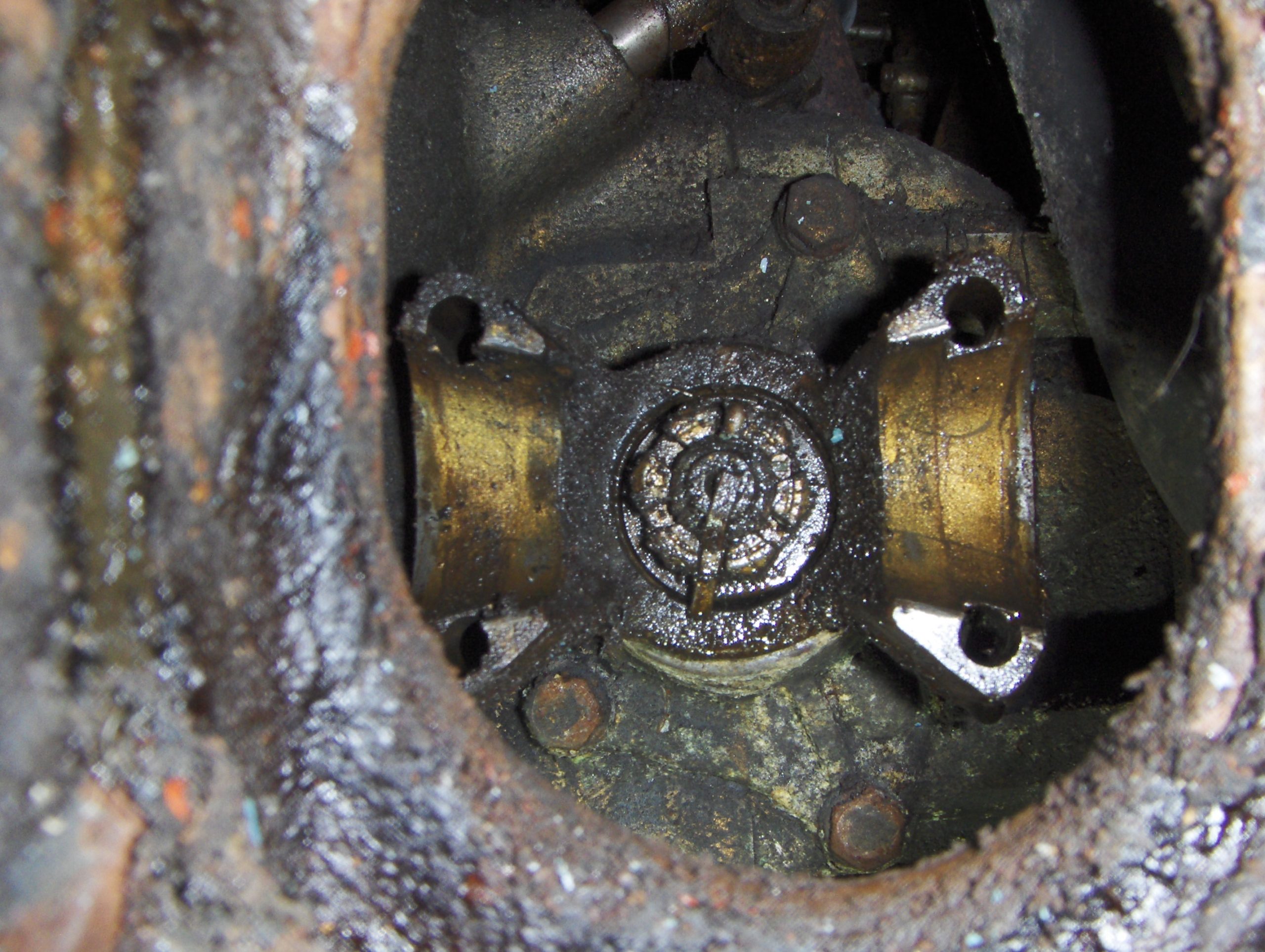
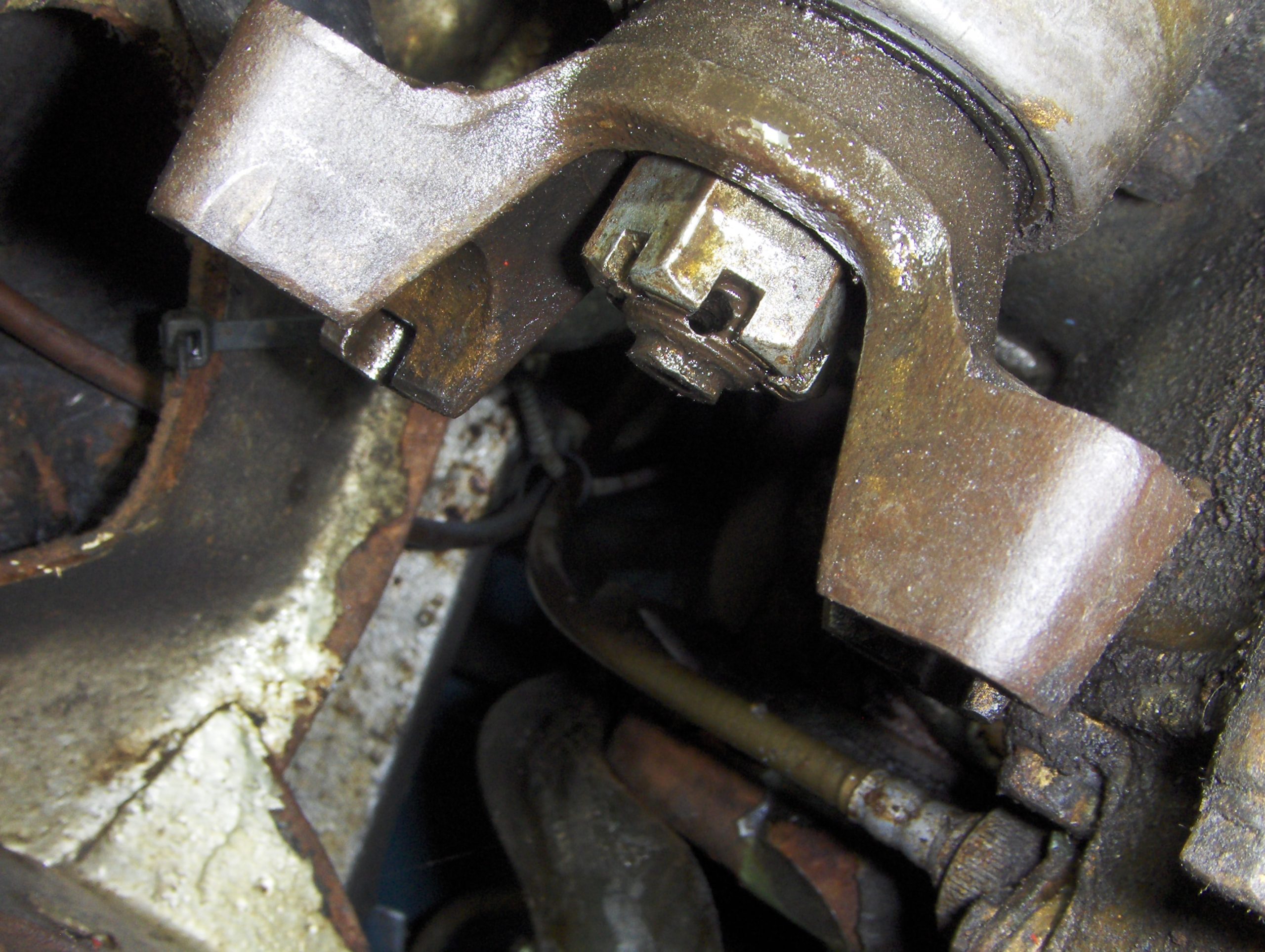
Note split pin hole not aligned (not even finger tight), and gap between nut and washer can be clearly seen).
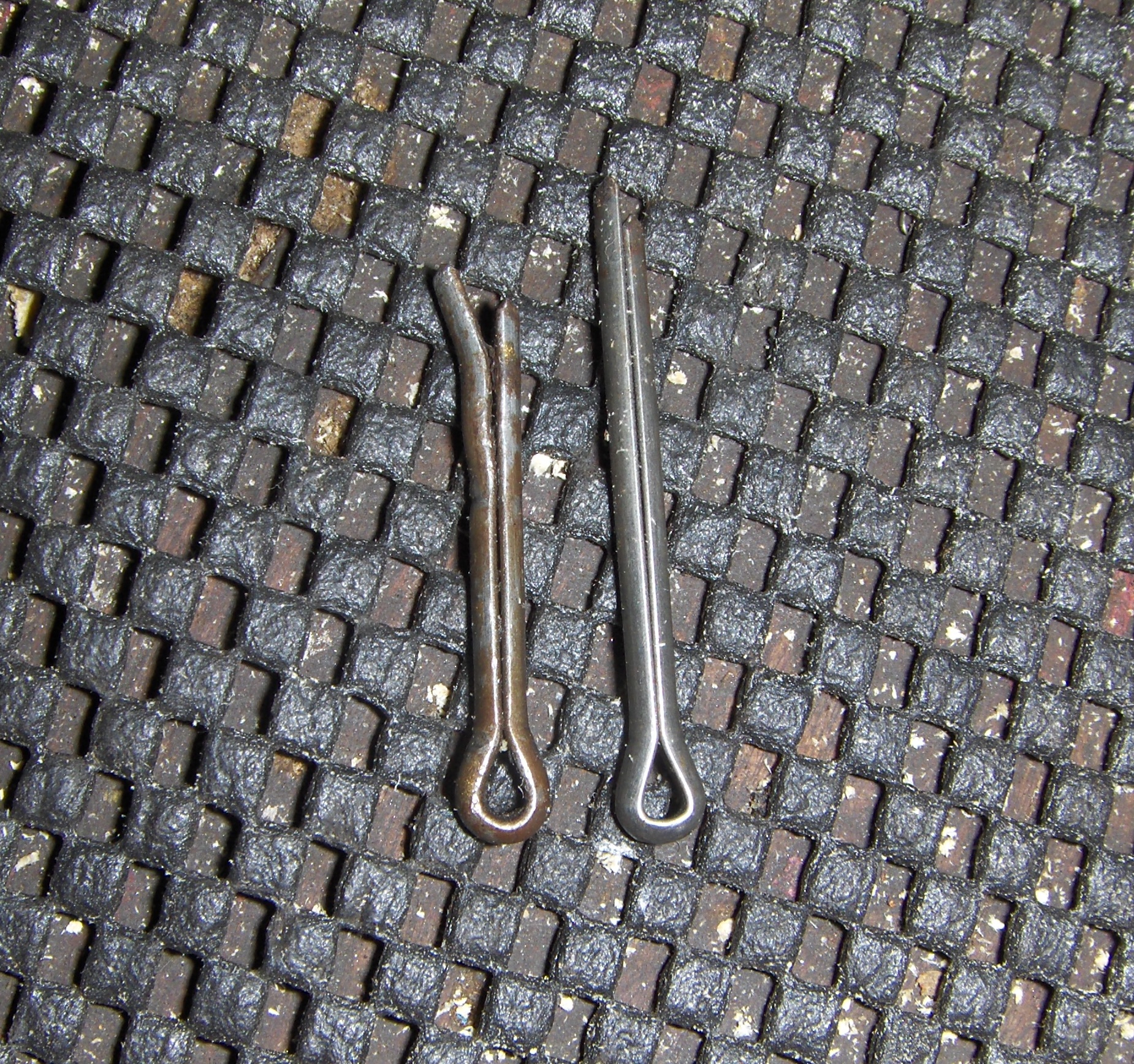
With securing split pin removed, quickly tightening the nut with a ring spanner before lunch had completely stopped weepage afterwards, so I started making the special tool needed to achieve recommended torque on the nut with some confidence. The problem, with the transmission in place, is simple: Somehow, underneath the car, in a confined space, the drive flange must be securely prevented from turning – while still allowing access for a 15/16 inch AF socket to tighten the flange nut. There was a steel BMC tool, part no 18G669, for this job, but it can be achieved by fabricating something suitable from a sturdy piece of timber. (See separate section)
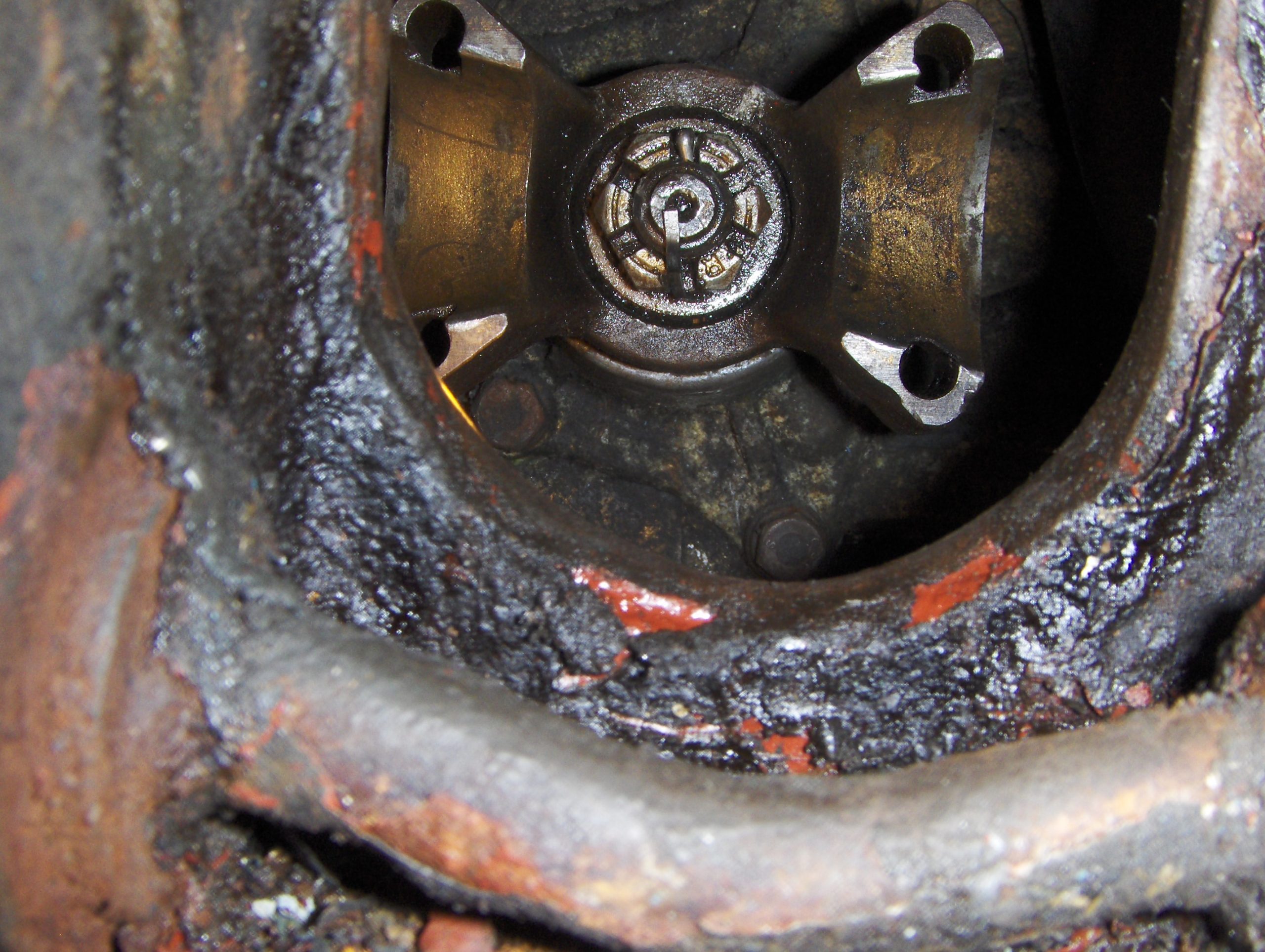
Looking ahead before starting re-assembly…
Before putting early Mini driveline components – on either side of the car – back together.
- Carefully examine the inner doughnut for signs of looseness or fatigue, particularly rubber deterioration as a result of mileage, or through long term oil contamination from engine/transmission leaks. Any looseness in key doughnut parts demands a new replacement.
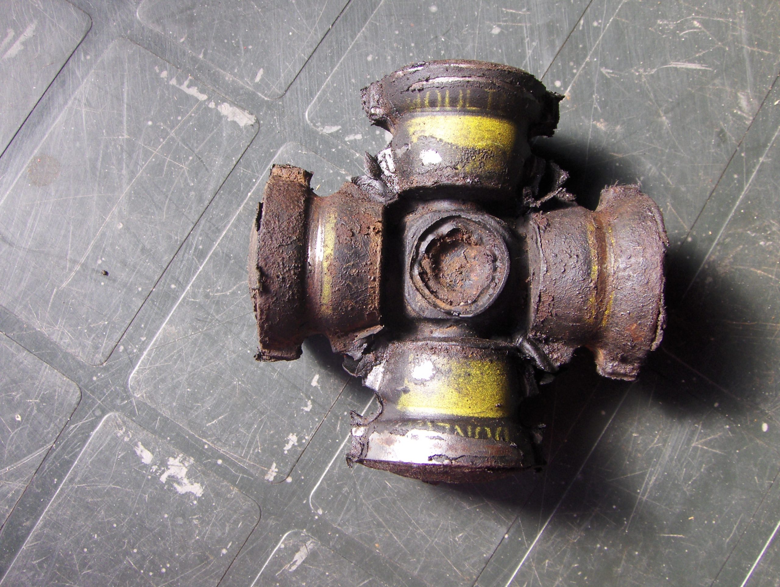
Cleaned up doughnut – early style but still in good condition. (Made by Dunlop). - When re-fitting a doughnut, ensure it is the right way round, some early versions need the central indentation facing towards the driving flange nut.
- Carefully clean and examine the removed U bolts. Some parts can get rusty. Look for stress points (shiny metal) just over half way along the straight lengths where the bolt nips into the doughnut locators. Excessive shine/wear here could suggest a failing doughnut. If in doubt about bolt condition, recheck the doughnut – and use new U bolts.
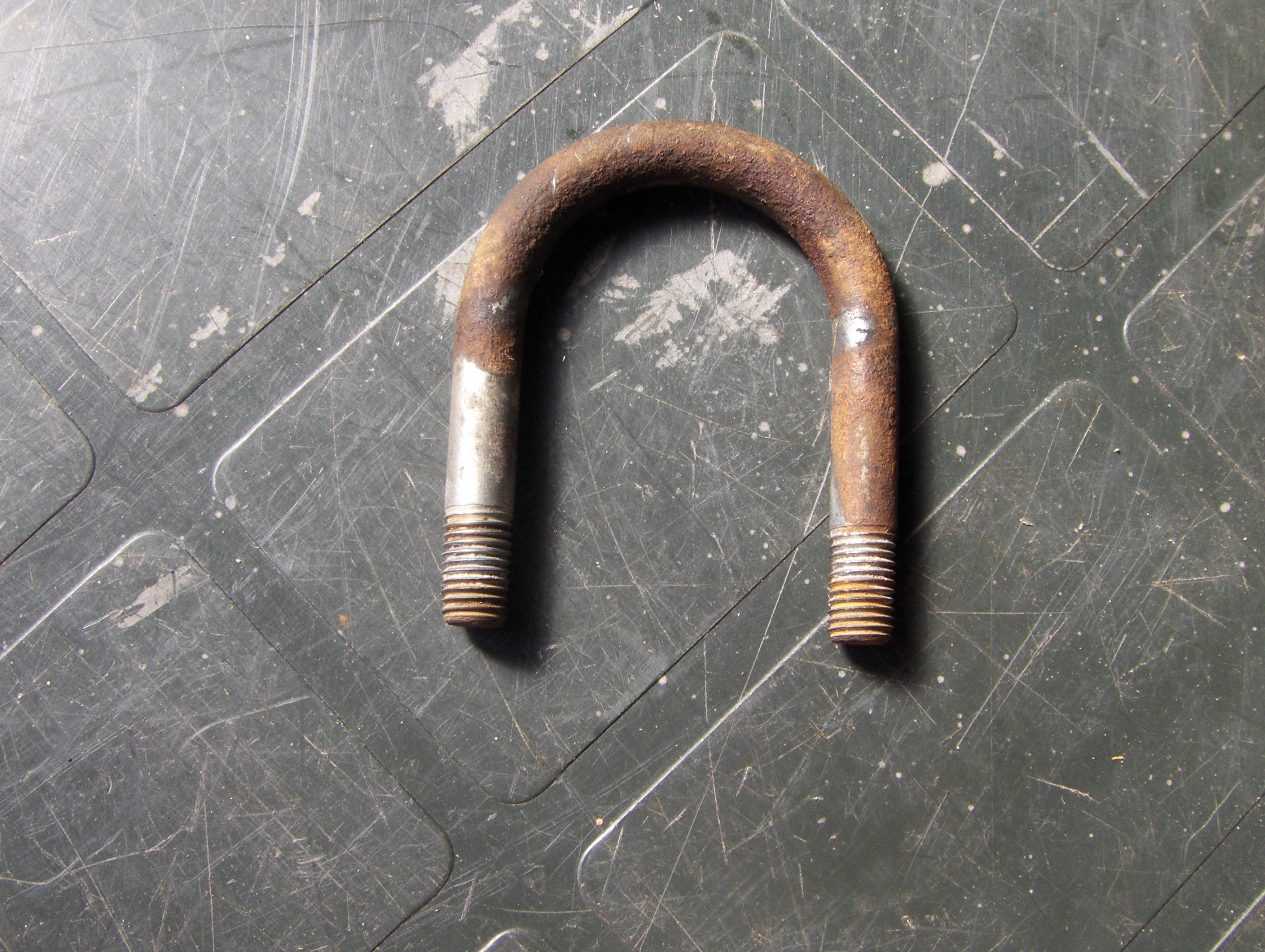
Cleaned U bolt, note shine midway along in rust on both sides indicating wear point. - Use new ‘Nyloc’ full nuts on these U bolts when reassembling. (The Workshop Manual cautions against using ‘deformed thread’ types – sometimes called “stiffnuts”)
- Ensure you have all required parts available before starting re-assembly. It’s really irritating to have to stop work midway until parts are obtained. Don’t forget tie-rod and swivel pin parts, and brake pipes/hoses/attachments.
- Check the condition of the drive shaft inner sliding joint and outer universal joint rubber boots: if either are deteriorating, cut, damaged or leaking grease, it’s an MoT fail; they must be replaced.
Re-assembly
Don’t you just love those aftermarket workshop manuals that say “re-assembly is a straightforward reversal of the dismantling procedure… “Sure it is, but it’s never quite that easy.” Start under the car with two U bolts, and mount the doughnut to the differential driving flange, nuts finger tight only until later. Manoeuvre the hub/drive shaft assembly on the trolley jack to the position where it was extracted, i.e. angled, forward of the driveshaft’s running line, so the driving flange addresses the subframe aperture at a slight angle. Start with the jack with hub set very low, and – avoiding the lower suspension arm – hook the lower edge of the flange over the lower ledge of the subframe aperture.
Check underneath that the upper edge of the flange appears in that slightly angled position, where its top left corner can come through the hole. Raise the trolley jack slowly, observing the driving flange position from the wheel arch, slightly adjusting position with a long screwdriver as necessary so the top left, then right, of the flange will enter the hole as the jack is raised and its horizontal position shifted rightwards and inwards. With the flange through the hole, gently rotate the shaft and push the assembly forward so the flange will correctly engage the doughnut. This should leave the shaft itself near horizontal, with the jack still bearing the weight.
Underneath the car, connect the driveshaft with the remaining U bolts, again finger tight only until the hub is on its swivel pins. Fit new bushes with removed washers to the front of the tie rod, nut finger tight nut to keep everything in the subframe mount, then use new components to attach the rod to the lower suspension arm – finger tight again. If you spotted slack in swivel pin mounts when dismantling, now’s the time to tackle that job.
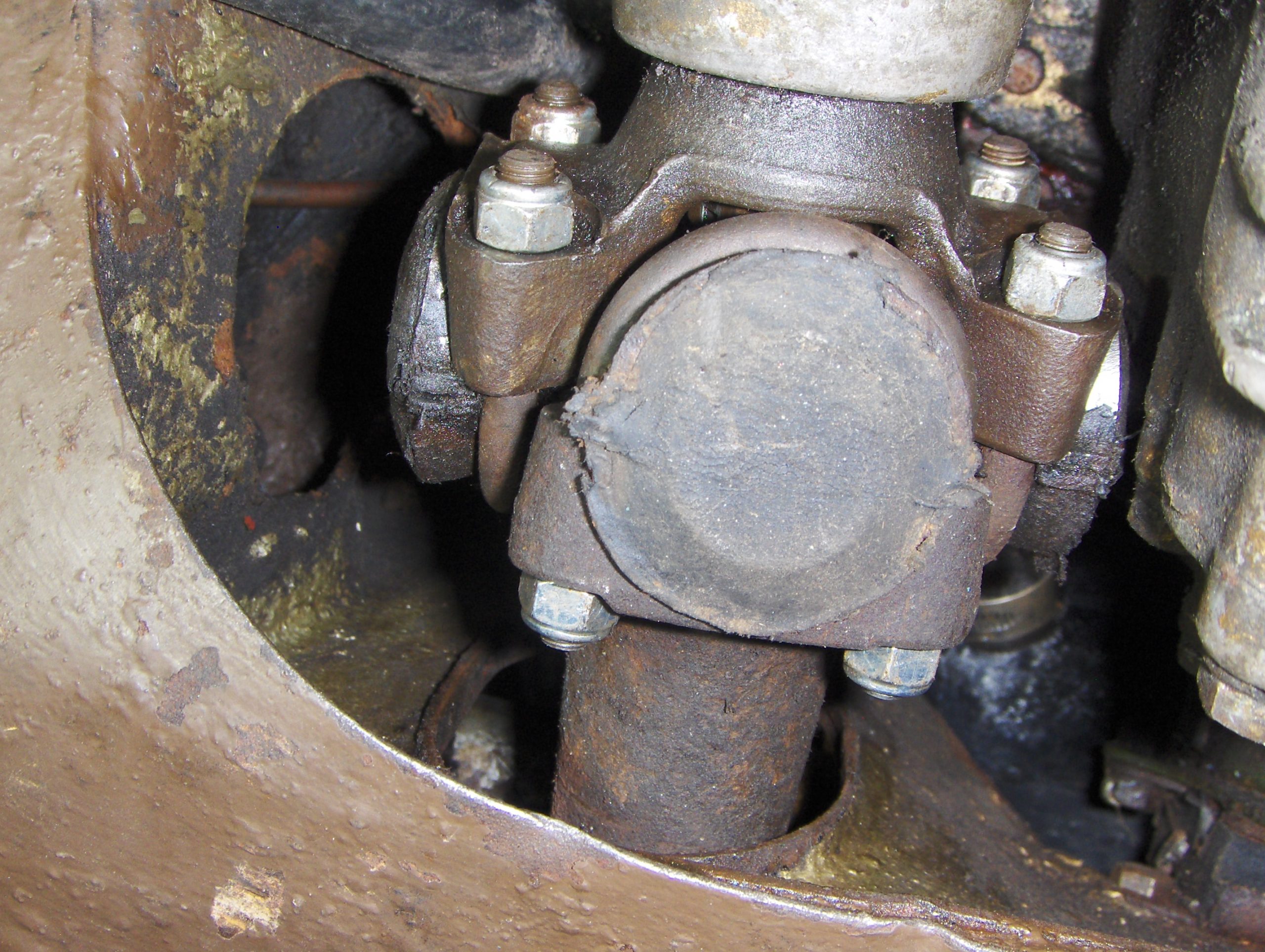
Next, locate the hub’s upper swivel pin in its mount, fit a new spring washer and hardened nut if available. Finger tighten the nut and follow by inserting the lower pin into its mount. Check the hub will rotate normally, then tighten all four Nyloc nuts on the doughnut U bolts, and check again for normal hub rotation. If there’s excessive friction (and it’s not brake drag) investigate! Tighten both swivel pin nuts, then both tie rod ends, and check the hub is free to both swivel and rotate. If it is, – having checked for zero slack in its sealed joint – attach and tighten the track rod end.
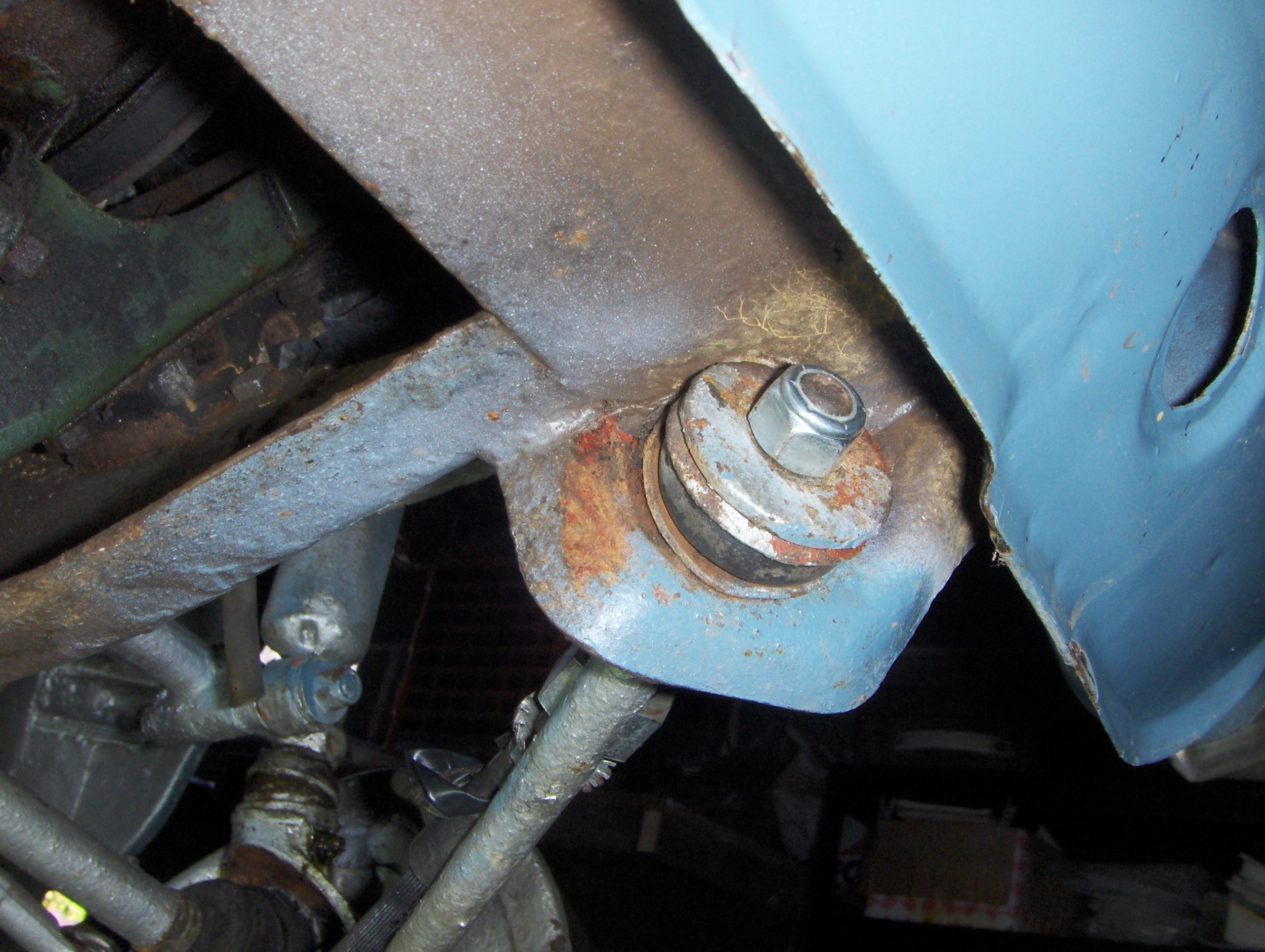
Finally, brake hose connection. If the metal pipe disconnected cleanly, check it for rust, especially on entering the union. If there’s doubt about its condition, don’t hesitate – replace it. Similarly, if brake hose examination reveals rust, damage or deterioration, fit a new hose. There is more than one part number for this hose: Get the right one for your specific car. Consider also the hose mounting nut condition (UNF thread, 15/16in spanner), which is found in both half- and full-nut types. Your choice of swings or roundabouts: Full nuts can make pipe union access problematic, but allow wonderful purchase for hose removal; a half nut allows easy union access, and reasonable purchase, but the exposed hose thread goes rusty… and radiator drain pipe discharge finds its way here! Whatever you decide, ensure the shakeproof washer is fitted on the hose thread on the outside of the subframe; it’s there to stop the hose turning, not to stop the nut tightening down…
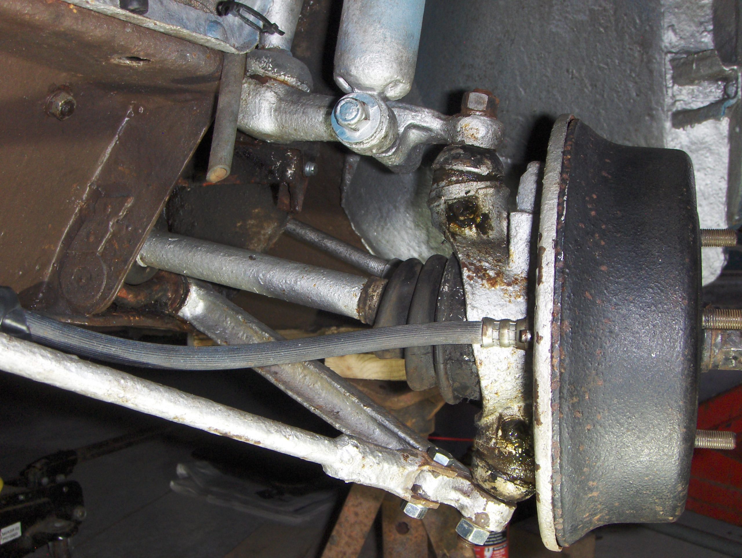
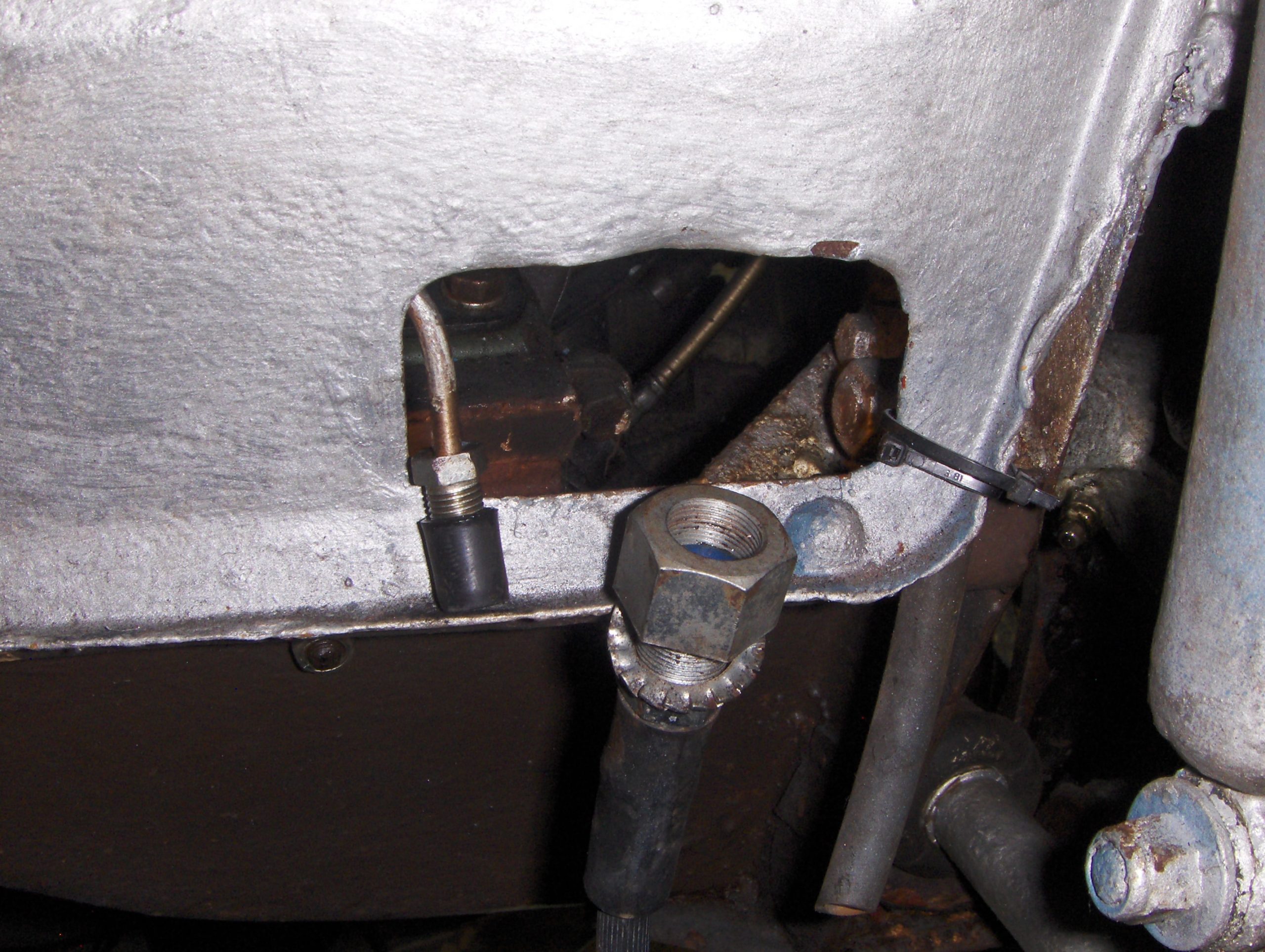
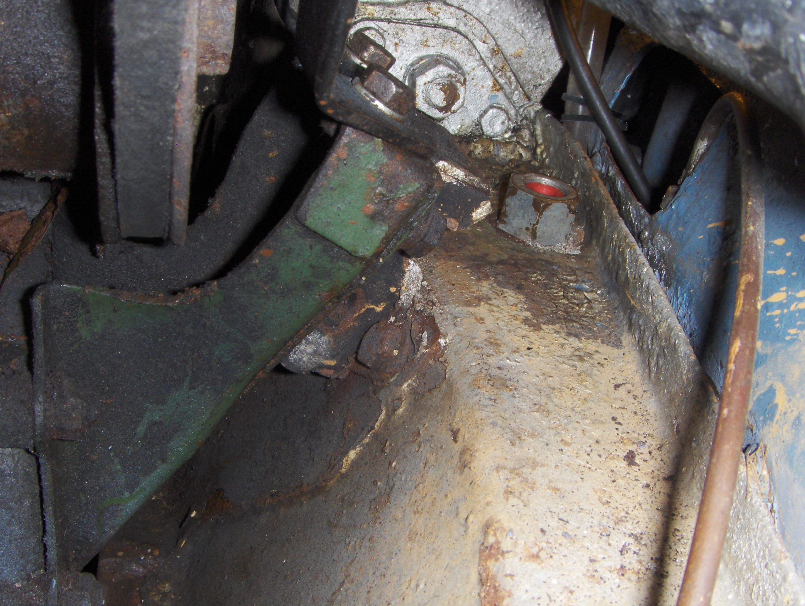
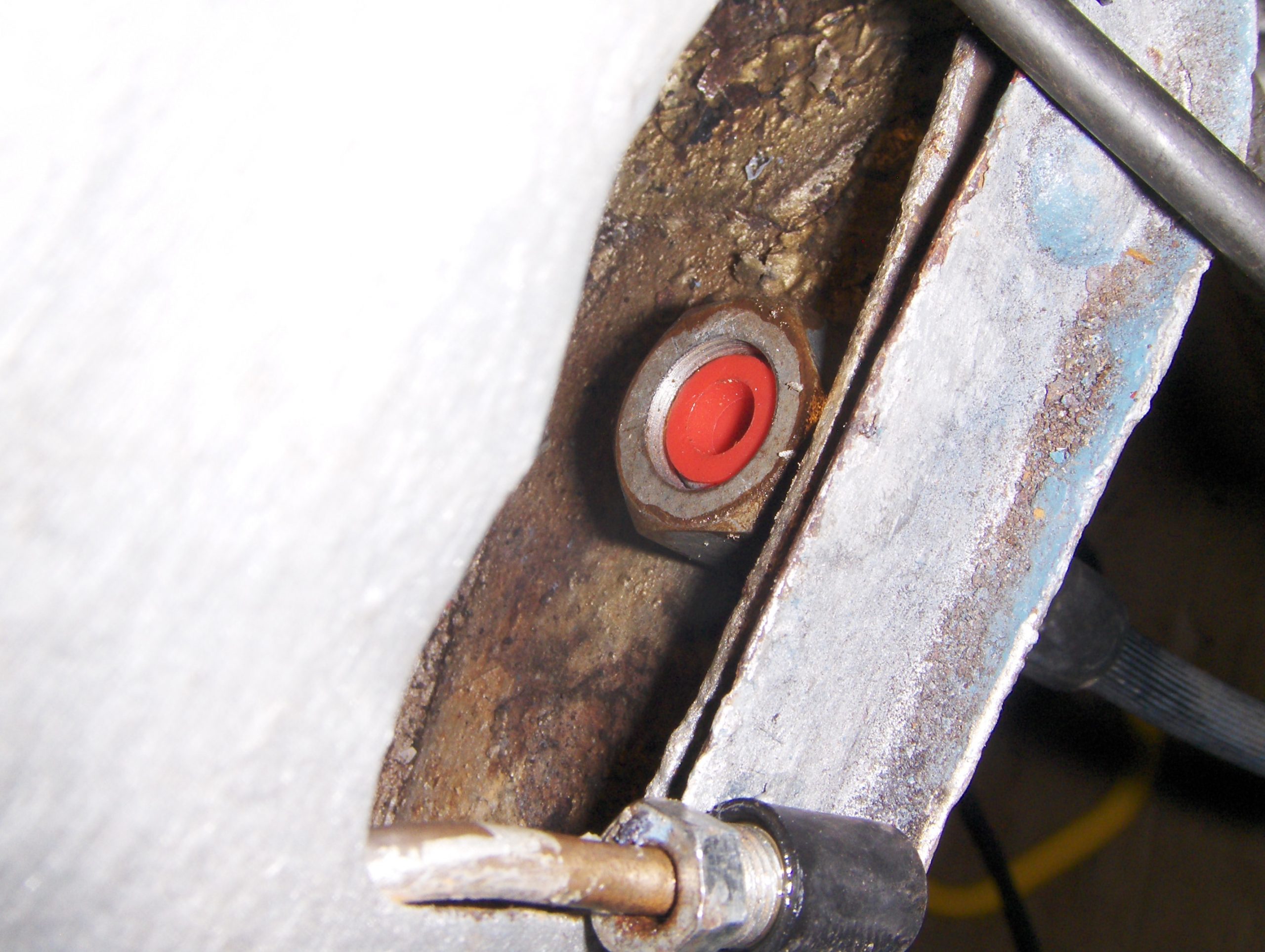
Finally, revisit all nuts checking for tightness, bleed and adjust the brakes, apply grease to the nipples if required, refit the wheel and you’re away. Happy motoring!
——————
Note on torque wrench settings.
Only two of the fixings which must be tightened in the procedures described here have official BMC workshop manual torque figures allocated. The quoted figures are:
Driving flange locknut – tighten to 70lb/ft and increase to align the castellated nut with the next split pin hole.
Top and bottom hub ball pin swivels – tighten to 35 to 40lb ft.
Experience has shown that the doughnut U bolt locking nuts should not be needlessly overtightened; a suggested torque figure is 10 to 15lb/ft
A special tool and procedure to hold differential flanges while tightening/untightening
Using the flange on the removed drive shaft as a reference, measure the centres of the U bolt mounting holes, and select a length of strong timber no more than 100mm wide and 14mm thick. These dimensions are a maximum because the subframe limits available working space.
The finished item should be chamfered for the top 160mm or so on both long edges – this will ease access to attach nuts and bolts. The actual length of timber required depends on your choice of working height above floor level, so use a flexible tape measure to measure from the highest point of the installed flange (when vertically aligned) to the horizontal ground surface below. I started with an approximate length, cutting to a shorter, more exact length once drilling was complete and I could temporarily align newly drilled holes (see below) with the car’s drive flange using loose bolts.

The timber should be long enough to securely stop rotation against the ground with the flange at an angle of slightly less than 90 degrees to the ground – remembering to take the direction of its travel into account as tightening/untightening force is applied. To make it as secure as possible under load, once the length was determined I cut off small triangles of timber from both bottom corners for a better angle of attack, and, once everything was assembled ready to go, used them as wedges tapped into the closure gap where timber and ground meet under load.
Mark up the timber to drill, at square, four 5/16 inch hole centres to the dimensions already obtained, centrally placed at least 1/2 inch from the timber top face, narrowest across the width. Follow with diagonal cross lines between opposing top and bottom centres to obtain and mark the centre point for a hole accommodating your 15/16 inch AF socket, which mates here with the nut (which is hidden behind the timber when mounted ready to use) After accurately drilling, expand the 5/16 inch holes to 3/8 inch – to allow wiggle room to easily get 1.25 inch UNF bolts through them and the flange – and some fitting space for the 15/16 inch socket. Use a hole cutter to make the large centre hole suiting your socket diameter. My socket required a hole 1.25inch (32mm) diameter. A small piece of 1/16 inch sheet steel with holes matching those drilled can be screwed across the top of the wood to reinforce the area if desired.
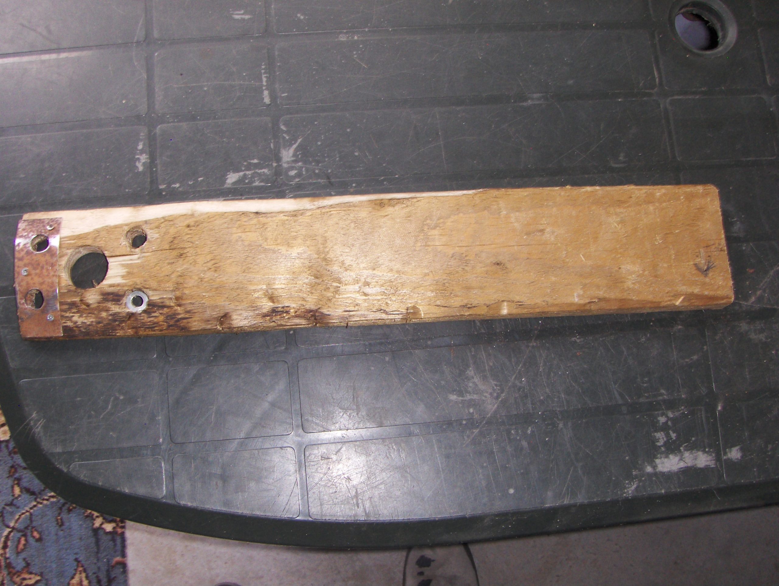
Ensure the flange nut split pin is removed, and carefully mark the end of the shaft with a painted line aligned with the split pin hole. This will allow insertion alignment to be checked with the tool still in place if the socket is removed.
Fit the tool to the car’s flange using four 1.25 inch bolts with large plain washers, and non-locking full nuts – facing outwards. Check that your socket mates easily with the castellated nut, and leave in position while making the four temporary bolts quite tight. It is unquestionably fiddly, but it can be done. You will need a long extension for the socket to connect the torque wrench through the drive shaft hole – and do make sure the car is secure before proceeding to untighten, which should be relatively easy.
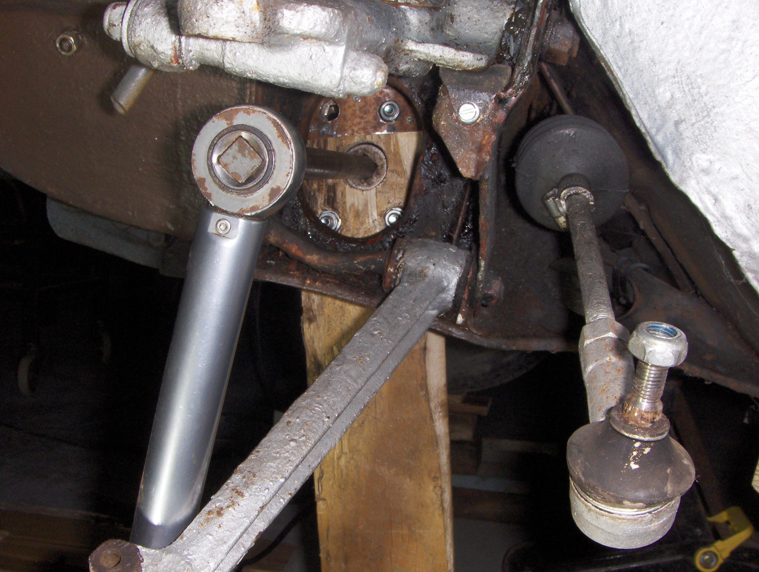
When tightening, withdrawing the socket will allow nut/split pin alignment checks as needed, but bear in mind that applying 70lb/ft tightening force or more here requires leverage close to that which will lift the car off its stands. If in any doubt about stability under these conditions, ask a helper to sit in the front of the car, on the side being worked on, while you tighten the nut – and keep a watchful eye for movement throughout.
When complete, remove the tool and fit a new split pin on the flange nut to finish.