Mysteries of the Instrument Voltage Stabiliser revealed…
Dave Moss explains and advises, in the first feature of his new ‘Need to Know’ series, covering various aspects of classic vehicle technicalities…
(Words and all images, including hand-drawn diagrams, by Dave).
If you have a car made by BMC or its successors anywhere between the 1960s and mid-1980s, it may have an instrument voltage stabiliser (IVS) originally made by Smiths Industries. Vehicle types include Jaguar, Triumph, Morris, MG and all Mini variations, but there are others. The IVS lives in a small, inconsequential rectangular metal box – often well hidden in dark corners. Its contents are typically low-tech – and usually function for years without trouble – so developing faults can pass unnoticed. Indeed in the early stages of decline the effects can be very subtle, making it difficult to tell anything is amiss.
The most obvious sign of misbehaviour is a fuel gauge which never reads full, often indicating something over half-full despite a brim-full tank. The linearity is also wrong as it falls towards empty, and readings might vary with engine speed. Electrically powered temperature gauges also misread – but the fuel gauge is most likely to give the game away. Occasionally also, fuel gauges read much higher than expected, staying at full long after instinct tells you it just cant be true..!
As the immediately obvious system components, in either case it’s easy to be fooled into thinking that the gauge or the fuel tank sender has gone wrong. They can be quite difficult to check, though if there’s access to the gauge sender connection – easy on early Mini saloons for instance – use a jumper lead to temporarily connect the sender wire to a good chassis earth. The gauge may rise slowly, but it should eventually read at the full mark.
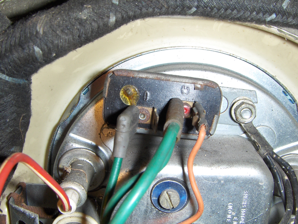
If it doesn’t, or you have symptoms as previously described and access is not easy, the IVS rates as a prime suspect. Seek it out, and check its connections – probably only two wires, connected to terminals “B” (for battery, and green if the manufacturer was obeying convention, and “I” for instruments – usually, but not always, lighter green. If all looks well, here’s how it works – and how to test it.
The IVS reduces the vehicle’s 12 volt electrical system to a nominal 10 volts – simply to power electrically powered instruments to Smiths specifications. Often it’s just the fuel gauge – though when fitted it also often powers a water temperature gauge, and possibly others in multi-instrument dashboards. Clearly a faulty IVS won’t affect non-electrical oil pressure, water, and oil temperature gauges.
A thermally-driven switching action is achieved as an electric current warms up a bimetallic arm, which bends away from contacts through which the said electric current is passing. The contacts disconnect, the current flow stops, and the arm cools down, re-makes contact, and the process restarts, and is repeated endlessly while the ignition is switched on (providing power to the “B” terminal).
The result is a voltage which instruments connected to the “I” terminal see as around 10 volts. Whether the engine is running or not is immaterial – the unit should provide this voltage within the range of the vehicle’s charging system. In some early units, a small screw adjusts the operating voltage.
However, measuring this unit’s 10 volt output isn’t as easy as it sounds. The switching action means that most of today’s widely available, modestly priced test-meters for general measurements on vehicles will not necessarily read 10 volts when connected to the “I” terminal. In fact, if its a typical modern digital meter, it may not read anything sensible at all – though you might be able so see the switching action through regular readout changes.
To check the unit is working correctly using such an instrument, you need a handful of modestly priced components, wired as shown.
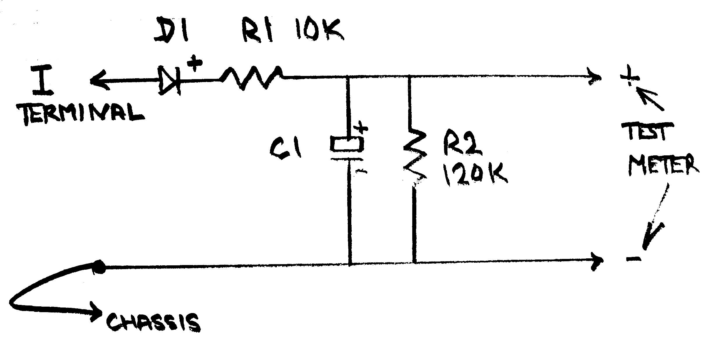
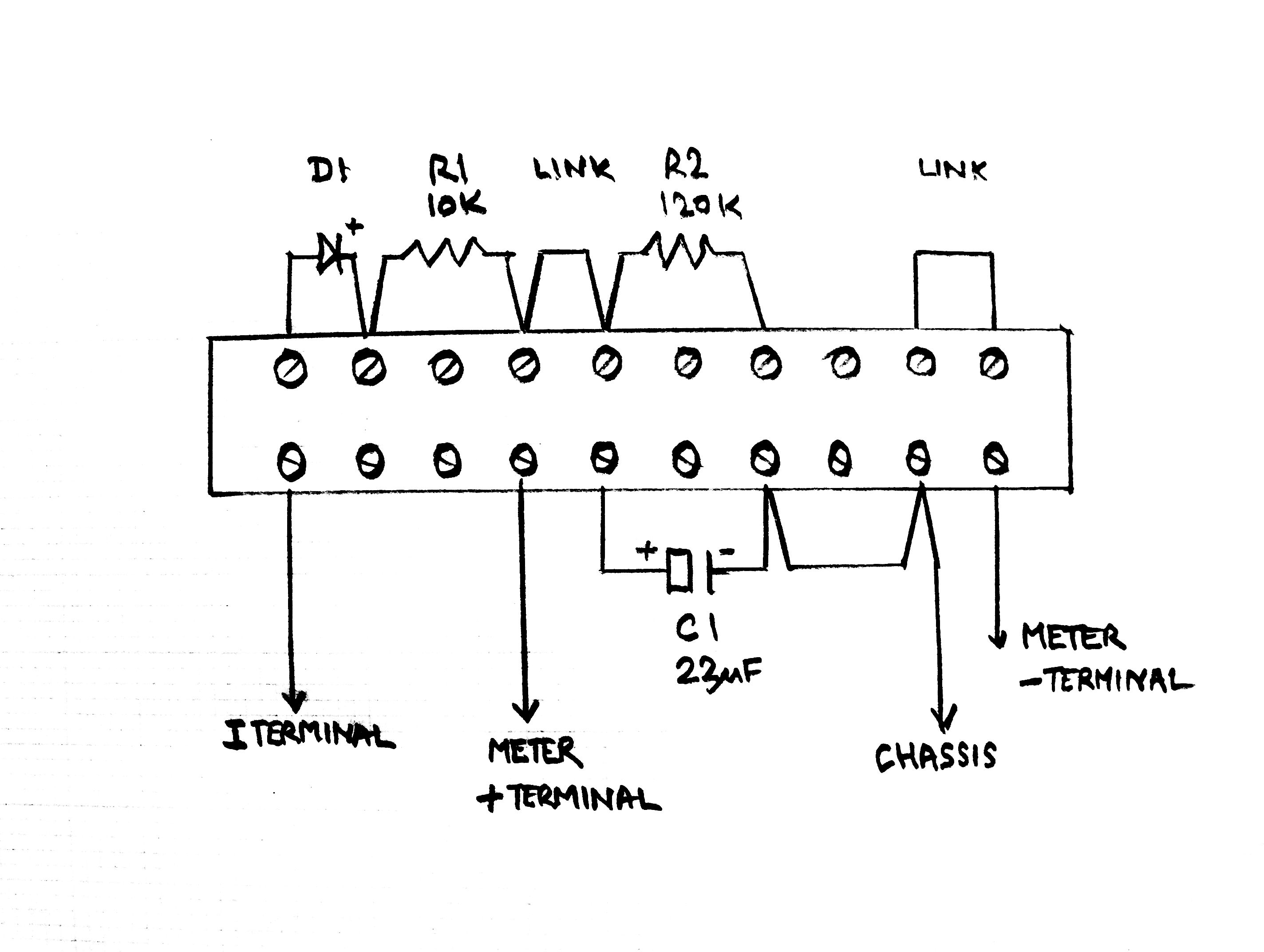
If you don’t have a small soldering iron, or the skills to use one, these parts can easily be wired on a screw terminal block available cheaply in DIY stores. Once wired, placing your digital meter probes as shown will provide a voltage readout equating to that on which the gauge(s) are operating. Using a professional quality voltmeter, or high quality ‘pointer on a scale’ multimeter such as an Avo or Taylor instrument, means you can leave out the 120k resistor labelled R2.
As is the way with basic electromechanical devices, 10 volts is more an average expectation than a mandatory requirement, and test meters vary too. These units might read anything between 9.75 and 10.25 volts when tested as above, but readings significantly outside that range, or varying greatly when in use, suggest replacement would be wise.
Though they do come in a small range of shapes and sizes and with alternative mounting fittings, original equipment IVS replacements can still be found. Today however, “solid state” units are available in similar packages – doing exactly the same job. They usually cost less, and, with no moving contacts, have potential for improved long term reliability. Here it’s important to use only a unit designed respectively for the negative or positive earth system of your vehicle. Older type units are sometimes also coded for polarity: Check for terminals labelled + or –, or a red dot, and install carefully if found. Units are also sometimes marked for installation facing upwards.
There’s an age-old question: Why add cost and complexity instead of simply using 12 volt instruments? The most plausible of several explanations put forward is that voltages in dynamo charging systems, on vehicles potentially used in temperatures ranging from +40 C to well below -20C, can vary between perhaps +15% and –12%… Though compensated voltage control helped, such wide changes on directly powered fuel gauges – monitoring a typically small fuel tank’s contents – could bring some pretty significant readout variations. This brings the possibility of running out of fuel with a quarter tank still showing… or switching on the headlights and seeing the fuel level fall towards zero!
It’s a good theory, but today a genuinely definitive explanation is elusive: if the designer or his successors could enlighten us, plenty of enthusiasts out here would love to know…
Test rig components/part numbers:
R1 – Resistor, 10k ohm, 10% or better tolerance, 0.25w minimum
CPC part no: RE03815.
R2 – Resistor , 120k ohm, 10% or better tolerance, 0.25w minimum
CPC Part no: RE03828.
D1 – Diode, type 1N4003
CPC Part no: SC07334.
C1 – Capacitor, Electrolytic or Tantalum. 22 microfarad (uF) 25v minimum
CC Part No: CA07172.
Component supplies:
These components should be readily available from any workshops undertaking radio, TV or hi-fi repairs. They may also be available from companies offering computer repair services. They can be mail ordered from companies such as cpc.co.uk for which part numbers are indicated above, but bear in mind because of the very modest cost of these components, suppliers frequently sell them in multiple packs rather than as single items.
Instrument voltage stabilisers – general part numbers list:
BMC/BL Smiths Use
13H3554 BR1305/00 Early cars, positive earth.
C34770 BR1310/00 Positive earth cars to about 1970.
C34770A BR1310/00 Negative earth cars to about 1984
(Note: It appears OE fitment under Smiths part number works with either polarity).
To read the second of our ‘Need to Know’ features by Dave Moss, and covering British wiring standards for classic cars, please click HERE.